An ultra-narrow gap welding device and method for welding pipe fittings

A welding device and pipe fitting welding technology, which is applied in the direction of welding equipment, welding accessories, arc welding equipment, etc., can solve problems such as settling defects, and achieve the effects of simple device, prevention of arc climbing, and low heat input

Active Publication Date: 2021-12-21
LANZHOU UNIVERSITY OF TECHNOLOGY
View PDF8 Cites 0 Cited by
  • Summary
  • Abstract
  • Description
  • Claims
  • Application Information

AI Technical Summary

Problems solved by technology

[0004] In view of the above problems, the present invention provides an ultra-narrow gap welding device and method for welding pipe fittings, which solves the problem of defects in the welding pool

Method used


Image

  • An ultra-narrow gap welding device and method for welding pipe fittings
  • An ultra-narrow gap welding device and method for welding pipe fittings
  • An ultra-narrow gap welding device and method for welding pipe fittings

Examples


Embodiment 1

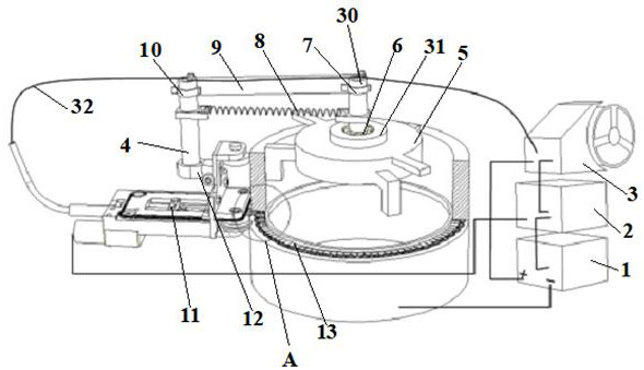
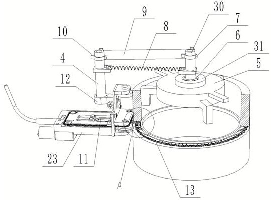
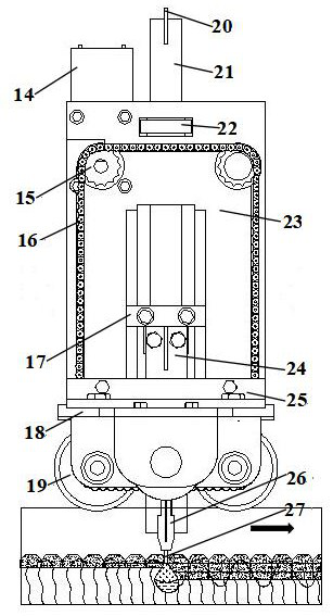
[0027] refer to Figure 1 to Figure 4, an ultra-narrow gap welding device for welding pipe fittings. The welding device includes a welding mechanism, a rotating mechanism and a positioning mechanism; the welding mechanism rotates around the positioning mechanism through the rotating mechanism, and the positioning mechanism is arranged inside the pipe to be welded. The positioning mechanism is mainly The position of the positioning welding mechanism in the groove, the rotating mechanism and the positioning mechanism are rotationally connected; the welding mechanism includes a motor 14, a first sprocket wheel 15, a chain 16, a support plate 18, a positioning wheel 19, a support frame 23, a plate welding torch 11; a support frame The front end of 23 is vertically provided with a support plate 18, the support plate 18 is fixedly installed on the support frame 23 through the L-shaped positioning plate 25, and the outer surface of the support plate 18 is evenly equipped with at least...

Embodiment 2

[0031] The present invention is mainly used for the welding of large pipe fittings and valve bodies. The groove gap used is between 4.5-5mm. Generally, the groove is assembled into an I-shaped groove of about 1.8°, and the thickness of each welding is 3-4mm. Left and right, in order to be able to weld in a narrow gap, the welding torch is a plate welding torch with a thickness of 3mm, and the flux is used to bring a restricted arc. The thickness is about 0.7mm, and its main components are limestone and fluorite. According to the composition of the weldment and welding quality It is required to properly add an appropriate amount of alloying elements, and the structure of the flux tape is a glass fiber net bonded with a flux sheet.

[0032] An ultra-narrow gap welding method for welding pipe fittings, comprising the following steps: performing derusting and degreasing operations on the welded parts before welding, and cleaning the surface of the welded part of the pipe fittings t...


PUM

PropertyMeasurementUnit
diameteraaaaaaaaaa
thicknessaaaaaaaaaa

Abstract

The invention discloses an ultra-narrow gap welding device and method for welding pipe fittings, and relates to the field of welding technology, wherein an ultra-narrow gap welding device for pipe fitting welding includes a welding mechanism, a rotating mechanism and a positioning mechanism The welding mechanism rotates around the positioning mechanism through the rotating mechanism, and the positioning mechanism is arranged inside the pipe to be welded, and the rotating mechanism is connected to the positioning mechanism in rotation; the present invention can carry out transverse welding in the groove with a small gap width, because the groove width is narrow , The energy of the welding line is small, the heat input in the welding process is low, the growth of the molten pool is effectively inhibited, and the collapse of the molten pool is prevented, which can not only effectively solve the defect of the molten pool, but also improve the welding production efficiency; the operation of the present invention It is convenient and easy to move, and overcomes the problems of difficult operation and high technical requirements for operation of large-scale equipment in on-site welding.

Description

technical field [0001] The invention relates to the field of welding technology, in particular to an ultra-narrow gap welding device and method for welding pipe fittings, which are suitable for on-site welding and defect repair of cast steel pipe fittings. Background technique [0002] At present, in the production of steam valves for power plant boilers, it is necessary to weld the cast valve body and the connecting pipe, the wall thickness of the connecting pipe is 60-120mm, and the inner diameter is 400-800mm. The existing welding method in the project is manual arc welding. The connecting pipe is placed vertically on the valve body that is inconvenient to turn over, a V-shaped groove is made, and the entire welding joint is completed by using the electrode arc all-position welding process. The welding quality is difficult to control. And welding production efficiency is low. [0003] The groove of the pipe fittings is assembled in a horizontal and transverse position, a...

Claims


Application Information

Patent Timeline
Patent Type & Authority Patents(China)
IPC IPC(8): B23K9/16B23K9/133B23K9/32
CPCB23K9/16B23K9/133B23K9/32
Inventor 朱亮董敏张爱华张兴有蒋小霞韩潇橦
Owner LANZHOU UNIVERSITY OF TECHNOLOGY
Why Eureka
Try Eureka