Backflow composite flat heat pipe

A flat heat pipe and composite technology, applied in the direction of indirect heat exchangers, lighting and heating equipment, etc., can solve the problems of unstable heat dissipation, heat source temperature rise, and greater impact on operating performance, so as to increase the critical heat flux density and shorten the The effect of reflow path and expansion of reflow space

Pending Publication Date: 2022-03-15
TIANJIN UNIV
View PDF0 Cites 0 Cited by
  • Summary
  • Abstract
  • Description
  • Claims
  • Application Information

AI Technical Summary

Problems solved by technology

[0004] The working medium backflow process of the flat heat pipe determines the heat flux that can be cooled. If the condensing working medium does not return in time, the working medium will burn dry at the evaporating end, causing the temperature of the heat source to rise sharply, and eventually the performance of the equipment will be reduced or even burned.
The working fluid return path of the traditional flat heat pipe is the porous structure of the liquid-absorbing core on the inner wall of the cavity. The working angle has a great influence on its operation performance, resulting in unstable heat dissipation effect in actual application, and even poor heat dissipation effect in some cases

Method used


Image

  • Backflow composite flat heat pipe
  • Backflow composite flat heat pipe
  • Backflow composite flat heat pipe

Examples


Embodiment Construction

[0029] The embodiments of the present invention will be described in detail below in conjunction with the accompanying drawings, so that the advantages and features of the present invention can be more easily understood by those skilled in the art, so as to clearly define the protection scope of the present invention.

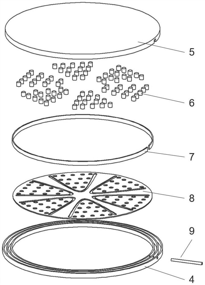
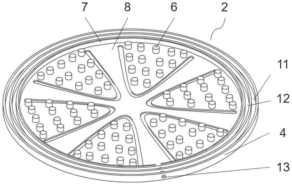
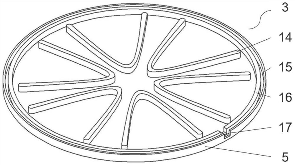
[0030] The invention discloses a reflux composite flat heat pipe 1. The system structure is as follows: figure 1 As shown, the structure of the evaporation end 2 is as follows figure 2 As shown, the structure of the condensation end 3 is as follows image 3 shown. This embodiment is a hollow cylindrical flat plate. The structural materials are selected as follows: the evaporation cover plate 4, the condensation cover plate 5 and the liquid filling pipe 9 are made of copper; the capillary return column 6, the wall surface liquid absorption core 7 and the bottom surface liquid absorption core 8 Deionized water.

[0031] In the figure, the evaporating end 2, ...


PUM


Abstract

The invention discloses a backflow combined type flat plate heat pipe which comprises an evaporation end, a condensation end, a liquid filling pipe and a liquid working medium. The liquid filling pipe and the condensation end are connected with the evaporation end to form a cavity containing a liquid working medium. The capillary reflux column and the side wall wick are arranged at the evaporation end; the evaporation end is super-hydrophilic, and the condensation end is super-hydrophobic; and the liquid working medium is deionized water. According to the non-wettability of the super-hydrophobic surface and the self-driven bounce phenomenon after liquid drop fusion, when the working angle of a system is that a condensation end is above, a liquid working medium quickly returns to an evaporation end by virtue of gravity, and capillary reflux does not need to play a role; when the condensation end is at the lower part, part of the condensation working medium returns to the evaporation end in a bouncing backflow mode, and the rest of the condensation working medium returns to the evaporation end in a capillary backflow mode through the capillary backflow column and the wall surface wick; meanwhile, a steam guide structure is arranged to promote liquid drops to flow back to the center of the evaporation end. Two backflow modes are combined, the backflow space of the flat heat pipe is expanded, the backflow path is shortened, and the backflow speed is increased.

Description

technical field [0001] The invention relates to the technical field of flat heat pipes, in particular to a reflow composite flat heat pipe. Background technique [0002] With the application of Internet of Things technology in many fields in real life, computing equipment is increasingly developing towards high performance and integration. The high degree of integration of electronic equipment makes the power density increase sharply, and the increased temperature makes the working performance decrease or even burn out. High heat flux has become an important factor restricting the further development of electronic equipment. [0003] The flat heat pipe is an efficient heat dissipation device, which is attached to the heat generating device, transfers the heat from the concentrated heat source to the external area and disperses it to a larger area, and can effectively reduce the temperature of the heat source. The structure of the flat heat pipe is a cavity filled with a wor...

Claims


Application Information

Patent Timeline
Patent Type & Authority Applications(China)
IPC IPC(8): F28D15/02F28D15/04
CPCF28D15/0233F28D15/046
Inventor 孙凯刘忠臣王天友
Owner TIANJIN UNIV
Why Eureka
Try Eureka