
Rain tight electrical box assembly for mounting of an electrical fan or fixture

a technology for mounting an electrical fan or fixture, which is applied in the direction of electrical cable installation, overhead installation, electrical apparatus, etc., can solve the problems of electrical shorts, no mounting holes provided, and conventional outdoor electrical boxes that do not provide adequate protection, and achieve the effect of eliminating the need for time-consuming field modifications and saving labor

Active Publication Date: 2016-10-11
ARLINGTON INDS
View PDF8 Cites 28 Cited by
  • Summary
  • Abstract
  • Description
  • Claims
  • Application Information

AI Technical Summary

Benefits of technology

The current invention is a rain-tight fan or fixture box assembly that enables secure and rain-tight mounting of electrical fixtures or fans to a structural member. This assembly simplifies the installation process of exposing equipment to the elements and eliminates the need for time-consuming field modifications. Additionally, it ensures that water stays out and the wiring stays dry. The assembly is also safe and secure, capable of supporting heavy equipment, and can be used with electrical cable or conduit.

Problems solved by technology

Unfortunately, conventional outdoor electrical boxes do not provide adequate protection from wind-driven rain and water spray at the connection of the electrical fan or fixture to the box.
Furthermore, there are typically no mounting holes provided for mounting to a structural member, and the installers drill holes in the electrical box wall to accommodate mounting screws.
When the mounting screws are installed, the screws and screw threads are exposed to the box enclosure and the wiring therein, which could lead to electrical shorts.
Furthermore, the top mounting surface of the canopy portion of an outdoor fan typically is much wider than a conventional outdoor box, thereby creating a lot of open space between the electrical box and the outer edge of the canopy.
This open area can allow water to build up in the canopy and thus lead to an electrical short or other unsafe condition.

Method used


Image

  • Rain tight electrical box assembly for mounting of an electrical fan or fixture
  • Rain tight electrical box assembly for mounting of an electrical fan or fixture
  • Rain tight electrical box assembly for mounting of an electrical fan or fixture

Examples


second embodiment

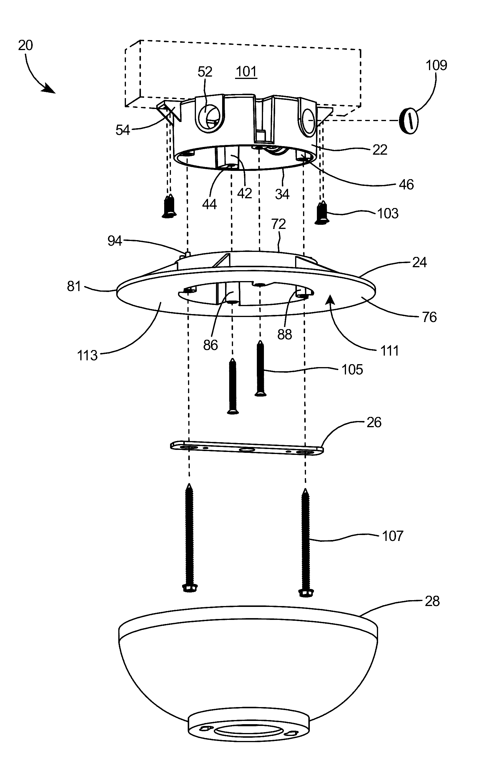
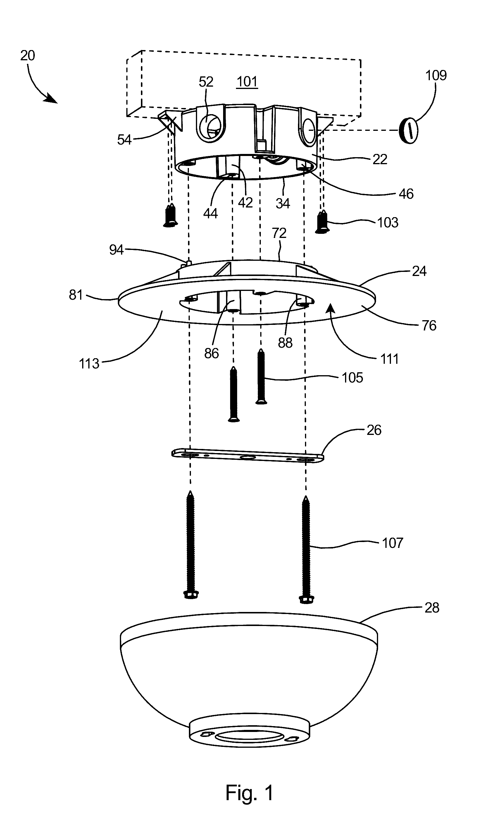
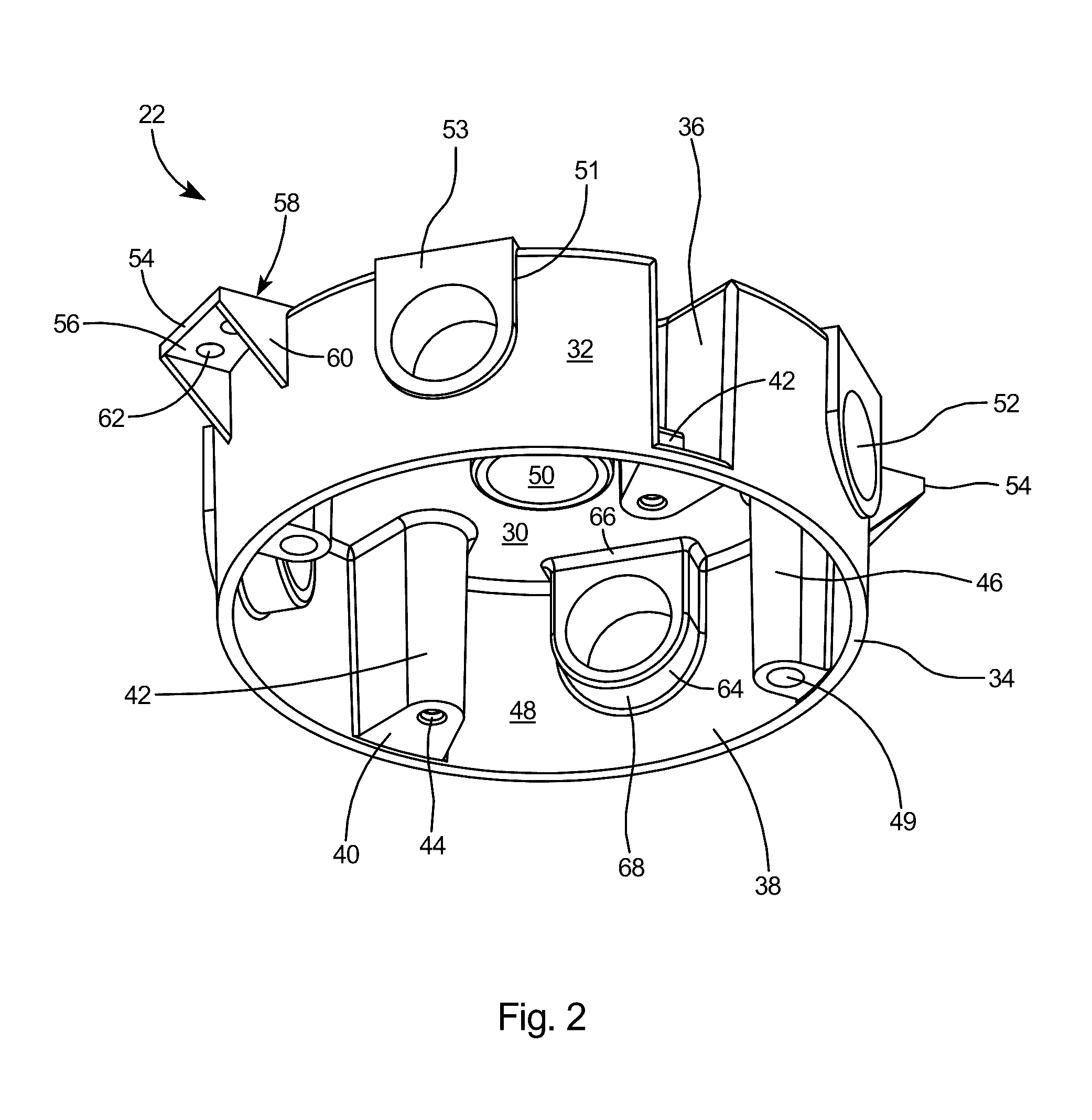
[0044]With reference to FIGS. 5 and 6, the electrical box 115. The electrical box 115 includes first bosses 42 and second bosses 46 and planar tabs 117 extending from the sidewall of the box, with the top side of the tabs 117 substantially coplanar with the back wall 30 of the box. Tabs 117 include apertures 119 therein and the interior of hub 51 may include threads 121. The inner surface 48 of sidewall 32 may include one or more flat portions 123 as shown.

[0045]As shown in FIG. 7, electrical box 115 includes first bosses 42 with bores 44 therein and sidewall recesses 36 preferably positioned 180° across from one another on the sidewall 32. FIG. 8 depicts the arrangement of the second bosses 46 with their internal bores 49 and the tabs 117 having their top surface substantially coplanar with the back wall 30 of the electrical box 115.

[0046]With reference to FIGS. 9-11 and 14, a second embodiment of the medallion 125 may include one or more flat portions 127 on the inner surface 129 ...

third embodiment

[0049]With reference to FIGS. 15-17 the electrical box 135 may be used in conjunction with a medallion for mounting of either an electrical fan or fixture (not shown) or may be used for direct mounting of a flood light (not shown). As shown in FIG. 15, the electrical box 135 includes a side boss 137 that is coextensive with each of the first bosses 42 and second bosses 46. Each of the side bosses 137 include a second bore 139 therein. As shown in FIG. 16, the second bores 139 are spaced at substantially 90° apart radially around the periphery of the electrical box sidewall 32. Second bores 139 are at a longer distance from the axial center 141 of the electrical box 32 than the bores 44 in first bosses 42 and the bores 49 in second bosses 46.

[0050]With reference to FIG. 18, electrical box 135 may be used for direct mounting of a flood light 143 thereto. In order to mount the flood light 143, fasteners 145 are driven through the base plate 147 of the flood light 143 and into the secon...


PUM


Abstract

A rain tight fan or fixture box assembly for mounting a fan or and electrical fixture to a structural member. The rain tight electrical box assembly includes an electrical box and a medallion. The electrical box includes a sidewall and a back wall defining a wiring enclosure and tabs extending from the sidewall. The medallion includes a sidewall having a top edge and a bottom edge, and a flange extending outward from the bottom edge around the periphery of the sidewall. A plurality of bosses extending from the sidewalls of both the electrical box and medallion provide a means for aligning and securing the medallion to the electrical box. Complementary sealing surfaces on the electrical box and medallion enable a rain-tight fit that seals the fan or fixture box assembly in a rain-tight fit. The electrical box is capable of accepting direct mounting of a flood light thereto.

Description

[0001]This application claims the priority of Provisional U.S. Patent Application Ser. No. 62 / 019,461 filed Jul. 1, 2014.FIELD OF THE INVENTION[0002]This invention relates to mounting of outdoor electrical fans, and specifically to a rain tight electrical box assembly for mounting an outdoor fan to a support member.BACKGROUND OF THE INVENTION[0003]Electrical fans or fixtures are commonly mounted in locations that are exposed to wind-driven rain and water spray, such as pool screen enclosures, open porches, lanais, outdoor kitchens and eating areas, pavilions, greenhouses, barns and more. The fans or fixtures are typically mounted to a structural member with a conventional flangeless electrical box. Unfortunately, conventional outdoor electrical boxes do not provide adequate protection from wind-driven rain and water spray at the connection of the electrical fan or fixture to the box. Furthermore, there are typically no mounting holes provided for mounting to a structural member, and...

Claims


Application Information

Patent Timeline
IPC IPC(8): H02G3/08H02G7/00
CPCH02G3/088H02G7/00H02G3/081H02G3/083H02G3/20
Inventor GRETZ, THOMAS J.
Owner ARLINGTON INDS
Learn More