Hybrid power architecture for controlling a lighting system

a technology of hybrid power architecture and lighting system, which is applied in the direction of emergency power supply arrangement, circuit arrangement, transmission system, etc., can solve the problems of high installation cost, high installation cost, and increase the cost to a significant amount, so as to reduce the installation cost, and reduce the installation cost. the effect of cost loss

Active Publication Date: 2016-10-11
SIGNIFY HLDG BV
View PDF14 Cites 17 Cited by
  • Summary
  • Abstract
  • Description
  • Claims
  • Application Information

AI Technical Summary

Benefits of technology

[0008]The present disclosure provides a power supplying unit for LED fixtures, troffers or linear fittings that include a power converter to convert class-1 power input to Class-2 power output and a DC constant voltage source to keep the power illuminated in case of power failure. A control element for controlling the intensity of light depending on the requirement of light, thus providing intelligence to the fixture is also connected through the power supplying unit. In one aspect, the present disclosure provides a power supplying unit to the LED fixtures where the control signals are distributed using the class-2 in a multi-conductor class-2 cable, thus reducing the installation cost by only requiring the cable to be pulled between the power supplying unit and the LED fixture, transmitting both control and power signals coherently. Furthermore the transmission of power in class 2 standard means that the maximum power to be transmitted is limited to 100 VA, which is not lethal as compared to convention class 1 120 / 277V AC. Therefore the installation can be done by a less trained, lost cost labor force, reducing the installation cost significantly.

Problems solved by technology

The cost associated with the purchasing and installing the lighting fixtures in a building is very high; which is further increased when controls are wired along with the lighting fixtures.
Further addition of emergency lighting controls in the lighting system increase the cost to a significant amount.
Thus the total cost per square feet for commissioning the control equipments is very high.

Method used


Image

  • Hybrid power architecture for controlling a lighting system
  • Hybrid power architecture for controlling a lighting system
  • Hybrid power architecture for controlling a lighting system

Examples


Embodiment Construction

[0015]In the following detailed description of embodiments of the invention, numerous specific details are set forth in order to provide a thorough understanding of the embodiment of invention. However, it will be obvious to a person skilled in art that the embodiments of invention may be practiced with or without these specific details. In other instances well known methods, procedures and components have not been described in details so as not to unnecessarily obscure aspects of the embodiments of the invention.

[0016]Furthermore, it will be clear that the invention is not limited to these embodiments only. Numerous modifications, changes, variations, substitutions and equivalents will be apparent to those skilled in the art, without parting from the spirit and scope of the invention.

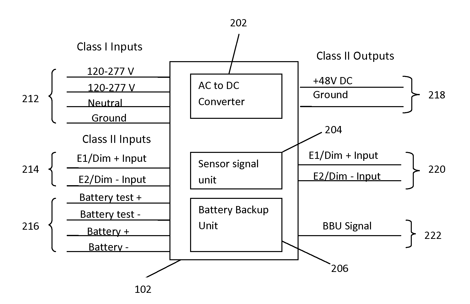
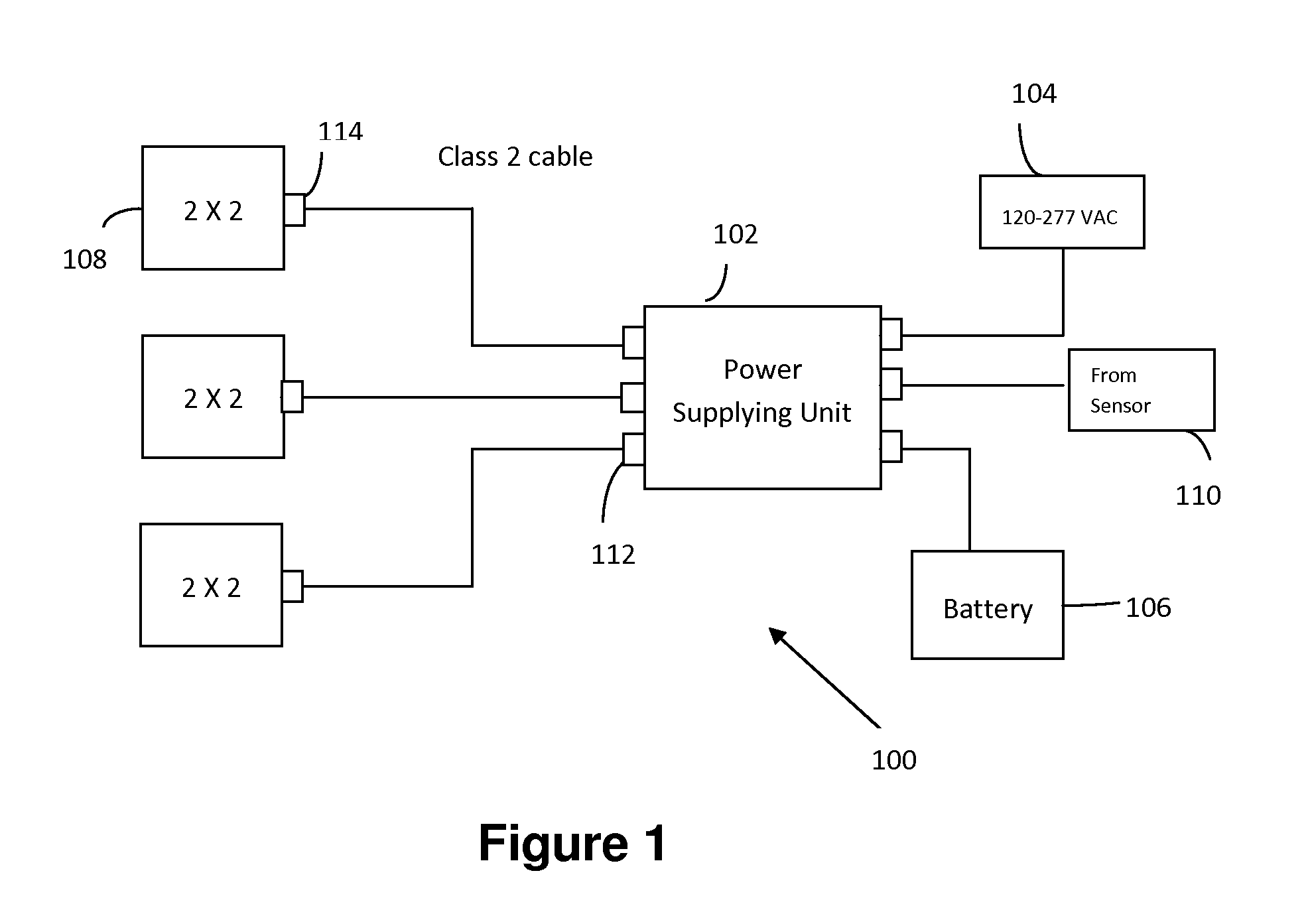
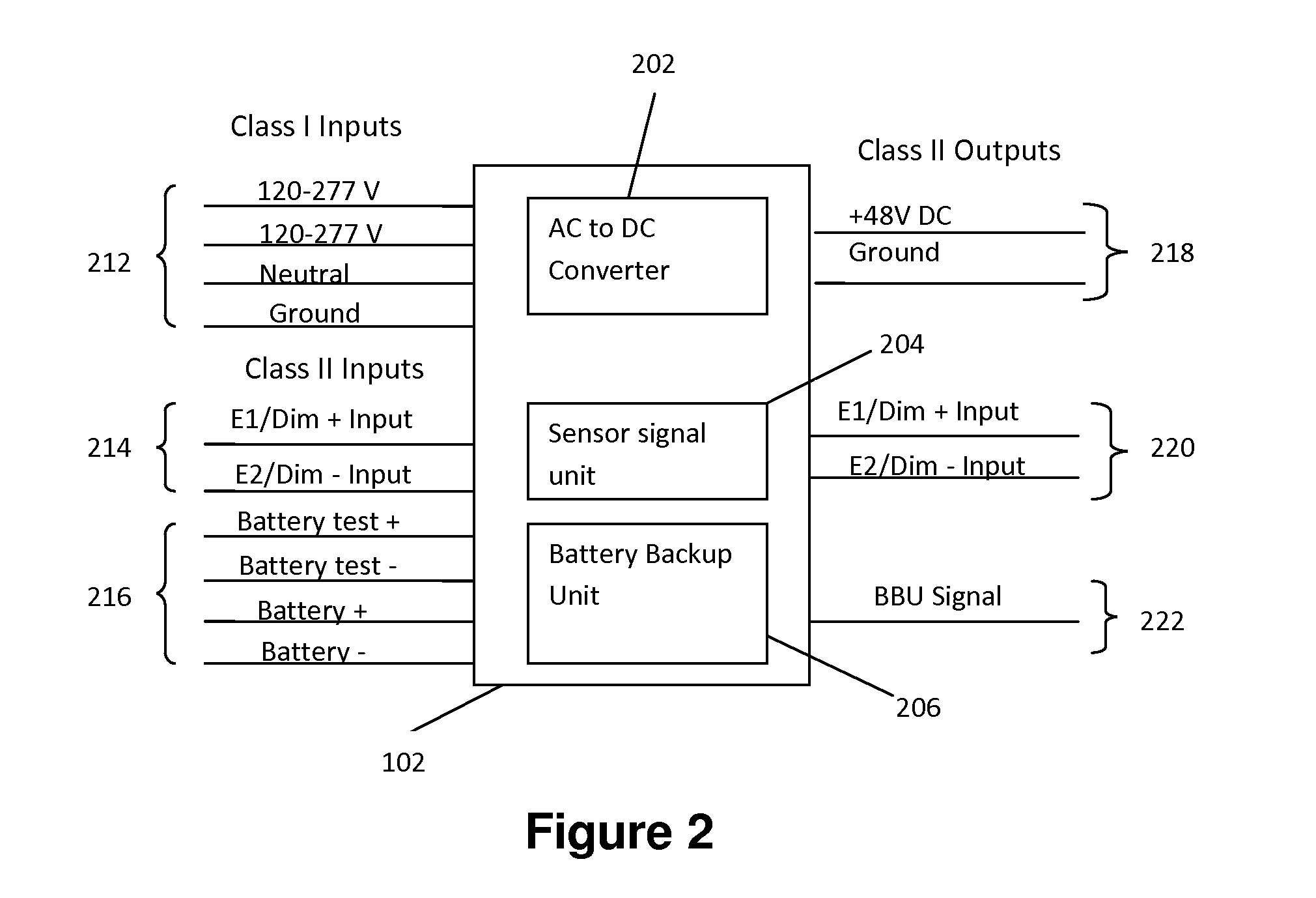
[0017]The present invention provides a hybrid power architecture to drive a LED fixture, troffer or a linear comprising a high efficiency AC to DC power converter that converts the class-1 AC input (10...


PUM


Abstract

A hybrid power architecture for lighting system that physically separates the conversion of AC-DC constant voltage power from the conversion of DC-DC constant current needed to drive the LEDs. The hybrid power architecture comprises a power converter to generate DC volt power, a battery backup unit for providing backup in the event of power failure and control architecture for controlling the intensity of the lighting system.

Description

FIELD OF THE INVENTION[0001]The present application relates to an apparatus for providing power to LED fixtures, and more particularly to a hybrid power architecture for LED based devices primarily used for illumination purposes.BACKGROUND[0002]Conservation and management of electrical power are a growing concern with regard to both cost and environmental impact. Lighting represents approximately one-third of electricity use in commercial buildings and more than one-half in lodging and retail. Commercial general lighting (troffers, linears and similar fixtures) light over 60% of the floor space in the US. Therefore lighting systems seem to have the largest potential of any known system to reduce the energy use.[0003]To address the issue of energy conservation, the use of energy efficient light emitting diodes (LEDs) for illumination is beginning to emerge as a lighting source. Apart from being energy efficient, LED lights have a long life, are durable and operate over a wide tempera...

Claims


Application Information

Patent Timeline
Patent Type & Authority Patents(United States)
IPC IPC(8): H02J9/00H02J3/00H05B33/08H02J9/06H05B44/00
CPCH05B33/0803H02J9/061Y10T307/344H05B45/00H05B45/31
Inventor BARNETSON, DONALDZHANG, JOHN X
Owner SIGNIFY HLDG BV
Why Eureka
Try Eureka