LiDAR scanner

a scanner and lidar technology, applied in the field of metals, can solve the problems of time-consuming and expensive processing of stereo imagery, and achieve the effect of low cos

Active Publication Date: 2016-10-18
UATC LLC
View PDF61 Cites 42 Cited by
  • Summary
  • Abstract
  • Description
  • Claims
  • Application Information

AI Technical Summary

Problems solved by technology

Historically to collect accurate distance and reflectance measurements one used photogrammetry techniques, but the process for extracting information from stereo imagery is both time consuming and expensive.

Method used


Image

  • LiDAR scanner
  • LiDAR scanner
  • LiDAR scanner

Examples


Embodiment Construction

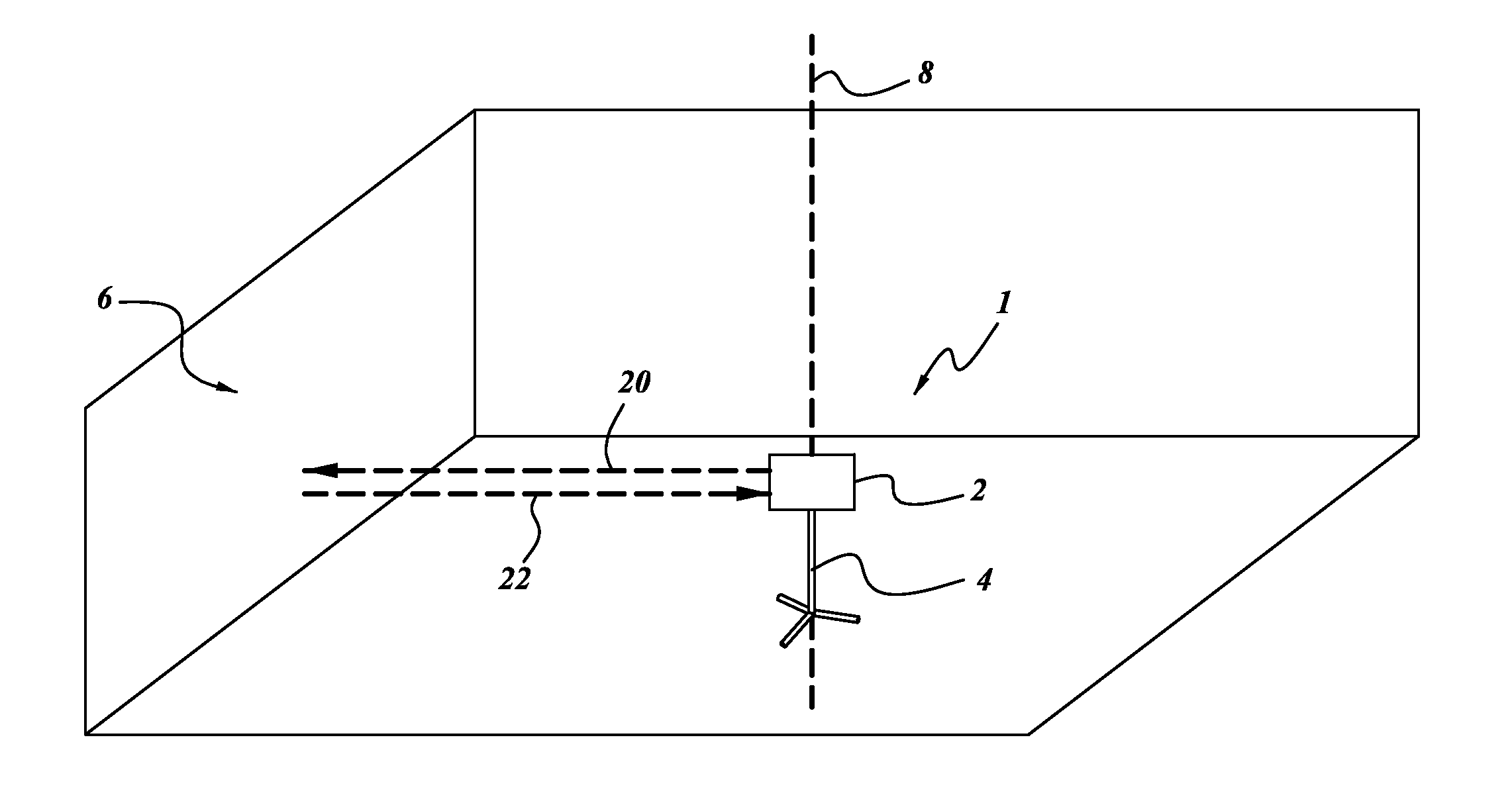
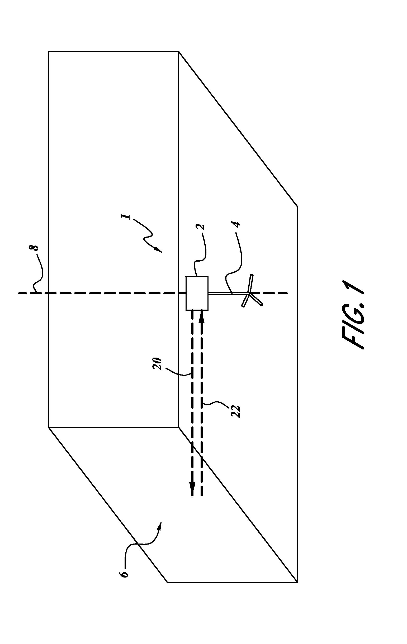
[0023]FIG. 1 depicts an embodiment position sensing device 1. The position sensing device is shown in an arbitrary environment, depicted as a walled room. However, it will be understood that the position sensing device 1 can be used in other environments such as a construction site, a mine, a laboratory, or other indoor and outdoor environments. The position sensing device 1 can be configured to measure at least one point, or further at least one spatial map of a portion of the environment, such as an object 6 in the room. For example, in the context of the room, the object 6 measured by the position sensing device 1 can be one or more walls of the room. In some embodiments the position sensing device 1 can measure a particular set of separate and discrete points, whereas in further embodiments the position sensing device 1 can measure a continuous span of points, as will be described further below. The measurement can be made using an electromagnetic pulse 20 (further described bel...


PUM


Abstract

A LiDAR sensor can include a laser, a directional sensor, a window, an electromagnetic pulse receiving sensor, and a processor. The laser can be configured to emit a narrow electromagnetic pulse. Further, the directional sensor can be configured to measure the direction of the narrow electromagnetic pulse emitted by the laser. The narrow emitted electromagnetic pulse can pass through the window. The pulse can then be reflected by at least the window and an object external from the LiDAR sensor, creating at least two reflected pulses. The electromagnetic pulse receiving sensor can be configured to measure the two reflected pulses resulting from the narrow pulse emitted by the laser. The processor can be configured to receive information from the sensors, indicating a position of the object relative to the LiDAR sensor. Further, the processor can be configured to measure the intensity of the pulse being reflected by the window.

Description

BACKGROUND OF THE INVENTIONS[0001]1. Field of the Inventions[0002]The present application relates to the field of metrology, and particularly to LiDAR sensors and related devices.[0003]2. Description of the Related Art[0004]The process for measuring distance and reflectance values for objects within an environment without touching those objects is of great interest to many industries including surveying, architecture, entertainment (character generated effects for movies and video games), construction, forensic and geography applications. Historically to collect accurate distance and reflectance measurements one used photogrammetry techniques, but the process for extracting information from stereo imagery is both time consuming and expensive. Over the past decade advances in Light Detecting and Ranging (LiDAR) technology have enabled practitioners to scan large area surfaces while collecting billions of data points, each with a precise latitude, longitude and elevation (x, y, z) val...

Claims


Application Information

Patent Timeline
Patent Type & Authority Patents(United States)
IPC IPC(8): G01C3/08G01S17/10G01S7/481G01S7/486G01S7/487G01S7/497G01S7/4865
CPCG01C3/08G01S7/4818G01S7/4865G01S7/4873G01S17/10G01S2007/4975G01S7/4808
Inventor SCHWARZ, BRENT S.HASLIM, JAMES A.ITURRARAN, NICHOLAS M.KARASOFF, MICHAEL D.
Owner UATC LLC
Why Eureka
Try Eureka