Device and method for vehicular invisible road illumination and imaging

a technology of invisible road and device, applied in the direction of reradiation, lighting and heating apparatus, instruments, etc., can solve the problems of limited vision, large percentage of all nighttime car accidents, and high accident ra

Inactive Publication Date: 2002-12-19
MATVEEV OLEG
View PDF7 Cites 33 Cited by
  • Summary
  • Abstract
  • Description
  • Claims
  • Application Information

AI Technical Summary

Problems solved by technology

It is known that depending on the circumstances large percentage of all nighttime car accidents happened due to inadequate illumination of the road.
One of the most common reasons of crashes is because drivers are blinded by oncoming cars.
On a per mile basis, driving at night is more than three times as likely to result in a fatality as driving during daylight.
While several factors affect these statistics, limited vision is one of the main reasons behind the high rate of accidents."
1. The UV light does not eliminate the necessity to have at least low beam headlights in the visible region of spectrum, which can be disturbing, interfering and dangerous for oncoming cars because of impairing visibility glare.
2. Many natural obstacles on the road do not produce good yield of fluorescence radiation in the visible region of spectrum (for example human body, trees, tires, stones, dents) and very often they can be better seen under illumination by visible but not UV light. If a driver would rely too much on the UV lamps he can miss important imaging information and this will lead to a higher probability of crashes.
3. The UV radiation might be hazardous from the environmental point of view. As known, many people are wearing sunglasses as protection against UV radiation to eliminate this hazard. In comparison with UV radiation from the sun which is normally seen as a scattered radiation (the brightest sun is normally above us in the sky) the UV radiation from cars will illuminate the eyes of pedestrians directly. The pedestrians will not see this radiation and will not close their eyes like if they were looking directly at the sun. At nighttime, the pupil of an eye is one-two order of magnitude larger than in the daytime. Because of this total exposure of people's eyes to UV can be much longer and more damaging. The brightness of the UV lamps is higher than the brightness of the sun and due to this, the total exposure of UV radiation per eye pixel can be one- two order of magnitude greater.
4. The UV lamp introduction will require additional US government multibillion dollars expenses to install better ...

Method used


Image

  • Device and method for vehicular invisible road illumination and imaging
  • Device and method for vehicular invisible road illumination and imaging
  • Device and method for vehicular invisible road illumination and imaging

Examples


first embodiment

[0082]

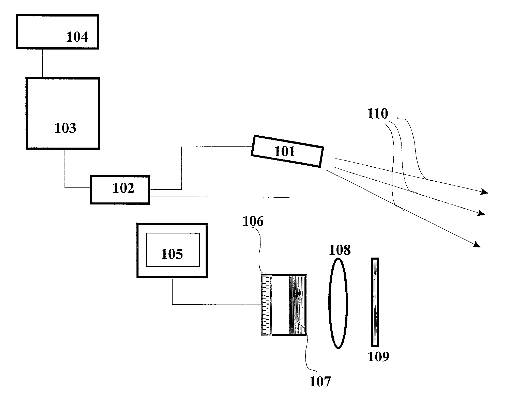
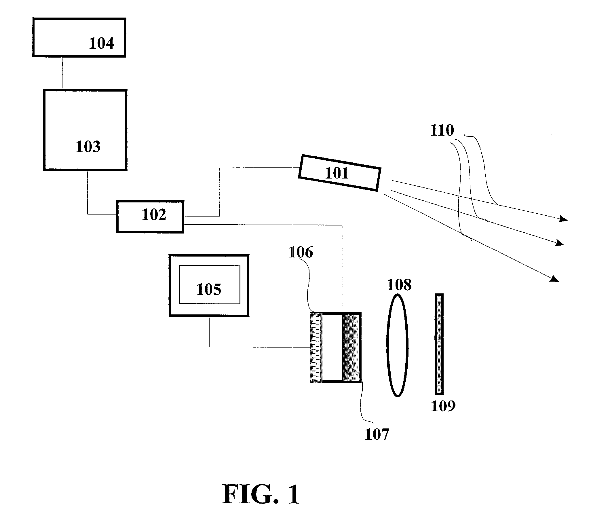
[0083] The description of this embodiment and the principles of operation of the invention can be understood from FIGS. 1, 2 and 2A. A pulsed road illuminating source of light 101 is used as a headlight of a vehicle and its radiation 110 is directed towards a direction of a vehicle movement to illuminate the road. If laser is used as a light source 101 its output may be homogenized via a fiber optic or light pipe or other such mean as known by those skilled in the art to uniformly illuminate the target area. The repetition rate of the pulses of the device 101 may be more than reciprocal time of eye inertia, preferably more than 5 Hz, although any rate can be used. The device 101 may be any type of pulsed source of light (for example: laser, pulsed arc discharge xenon lamps, electrodeless discharge lamp, light emitting diode etc.) illuminating in the invisible for human eye spectrum about 0.19-0.45 and 0.7-5 .mu.m. The spectral range of road illuminating device 101 may be in an...

second embodiment

[0121]

[0122] To increase reliability for the whole system also for the most demanding type of vehicles like police, ambulance, fire rescue additional improvement is included. For these purposes an additional generator is included, triggering electromagnetic pulse with electromagnetic frequency of its radiation different in comparison with road illuminating pulse. This additional triggering pulse is generated before road illuminating pulse with predetermined and the same for all vehicles time difference. The radiation from the additional generator is directed in the same direction as laser pulse from illuminating pulsed laser.

[0123] The technique described above can be called an ultra fast synchronized imaging technology Thus another preferred embodiment of ultra fast synchronized vehicular imaging system with invisible headlights is provided by this invention. The principle of operation can be understood from FIGS. 3 and 4. In comparison with the first embodiment of this invention, ...


PUM


Abstract

A device and method for vehicular invisible road illumination and imaging is provided. The device includes invisible for human eye and precisely synchronized for all vehicles pulsed laser or nonlaser sources of light to illuminate the road. The design and method of the invention involves providing a low probability of being blinded by oncoming vehicles and illumination of the road by light pulses which are shorter than the time which is necessary for the light pulse to travel the illuminated distance observed by the driver. Using a timing signal acquired from at least one satellite global positioning system, the period between the illuminating pulses is set the same for all vehicles with a high level of precision. The period between the illuminating pulses is divided into a predetermined number of time zones with a predetermined duration for each zone. Each predetermined time zone is assigned to a predetermined group of vehicles, for example, for military, government, law enforcement, ambulance, fire rescue, trucks, luxury vehicles, small, large vehicles etc. In order to further decrease the probability of being blinded by oncoming vehicles and also to reduce the necessary pulse energy of the illumination laser, the imaging system uses gated, spectrally selective imaging detectors with a luminosity-resolving power product at least 104 cm2 Sr. To increase the reliability for the whole system, especially for the most demanding types of vehicles such as police, ambulance and fire rescue, an additional improvement is included. For these purposes an additional generator of triggering pulse is included which illuminates an electromagnetic pulse of a different frequency from that which is used to illuminate the road. This additional triggering pulse is generated prior to the pulse which illuminates the road with a predetermined time difference, precisely set for all vehicles.

Description

[0001] Reference is hereby made to confidential invention disclosure "Invisible headlights of car for road illumination" for the Office of Technology Licensing, University of Florida, Gainesville Fla. UF#10373 filed Jun. 1, 2000 and to provisional patent application "Invisible headlights of car for road illumination" Ser. No. 60 / 295,699 filed Jun. 5, 2001, the benefits, of the filing dates of which is clamed herein.[0002] 1. Field of the Invention[0003] The present invention relates to nighttime driving and nighttime invisible for oncoming vehicles illumination of the road using pulsed laser and other non-laser sources of light.[0004] 2. Discussion of the Related Art[0005] It is known that depending on the circumstances large percentage of all nighttime car accidents happened due to inadequate illumination of the road. One of the most common reasons of crashes is because drivers are blinded by oncoming cars. As known [see for example http: / / www.nhtsa.dot.gov / people / ncsa / ovrfacts.htm...

Claims


Application Information

Patent Timeline
IPC IPC(8): B60Q1/14G01S5/14G01S7/484G01S7/487G01S7/51G01S17/18G01S17/86G01S17/88G01S17/89G01S17/931G01S19/48
CPCB60Q1/14B60Q1/1415G01S7/484G01S7/487G01S7/51G01S19/14G01S17/107G01S17/88G01S17/89G01S17/936G01S17/023G01S17/18G01S17/86G01S17/931
Inventor MATVEEV, OLEG
Owner MATVEEV OLEG
Why Eureka
Try Eureka