Hybrid welding method and hybrid welding equipment for laser electromagnetic pulse

An electromagnetic pulse and hybrid welding technology, which is applied in laser welding equipment, welding equipment, metal processing equipment, etc., can solve problems such as fatigue performance, fast solidification speed, and high-temperature evaporation of alloy elements, and achieve high-precision and high-quality manufacturing and upgrade Weld microstructure and properties, the effect of refining weld grains

Active Publication Date: 2014-04-23
武汉飞能达激光技术有限公司
View PDF8 Cites 33 Cited by
  • Summary
  • Abstract
  • Description
  • Claims
  • Application Information

AI Technical Summary

Problems solved by technology

[0003] Although the heat input and thermal influence of laser welding are much smaller than the traditional resistance welding and arc welding processes, as a fusion welding process, its biggest problem is that the thermal deformation caused by heat input still exists, which still seriously affects the assembly accuracy of components in many cases. and the overall performance of the structure, especially the fatigue performance
Secondly, when laser welding aluminum alloy, magnesium alloy, titanium alloy and other metal materials, the laser pinholes will be unstable during the welding process due to the low absorption rate of the material itself and the existence of alloy elements with low melting point and high boiling point. , in some cases there are problems of too fast solidification and high temperature evaporation of alloying elements
These problems lead to metallurgical defects such as pores, cracks, and poor forming in welded joints, which seriously affect the mechanical properties of joints.
Studies that have been carried out have shown that under single laser welding conditions, it is difficult to effectively control whether it is welding thermal deformation or metallurgical defects of light-weight welded laser joints
Moreover, these adverse effects are more pronounced in laser continuous seam welding because of the continuous build-up of heat and the dynamic movement of the laser pinhole

Method used


Image

  • Hybrid welding method and hybrid welding equipment for laser electromagnetic pulse
  • Hybrid welding method and hybrid welding equipment for laser electromagnetic pulse
  • Hybrid welding method and hybrid welding equipment for laser electromagnetic pulse

Examples


Embodiment 1

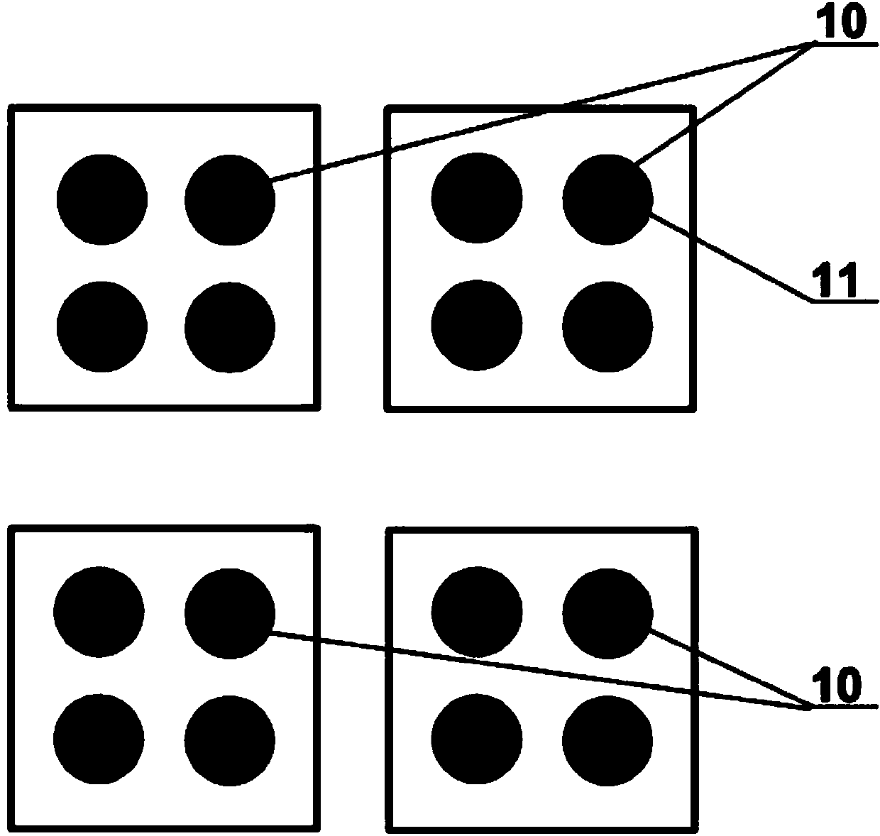
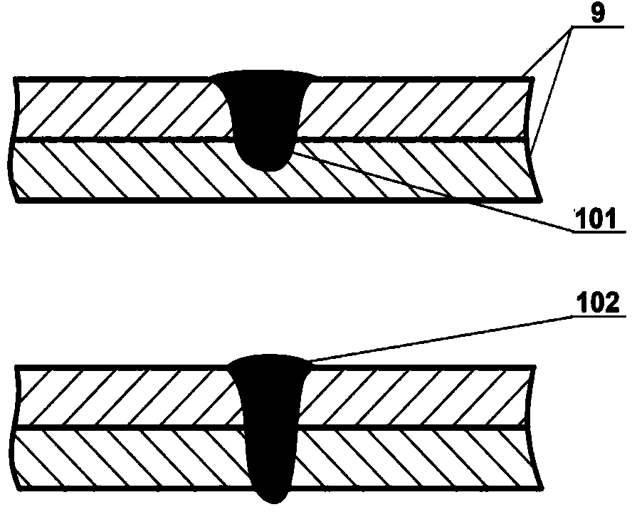
[0082] In this example, the welding workpiece 9 is a 2219 aluminum alloy cylindrical structure with a plate thickness of 2 mm, a diameter of 3.5 m and a height of 3 m. The welding requirements are upper and lower lap spot welding (the thickness of the welding point after lap is 4 mm). Figure 18 The laser electromagnetic pulse composite spot welding equipment shown is selected by the fiber laser and laser galvanometer scanning and focusing method (the shape and area of ​​the welding spot can be controlled by the laser beam swing scanning), the laser focal length is 300mm, and the shape of the welding spot of the welding seam is a solid circle. shape, and the cross-sectional feature is an unpenetrated form.

[0083] The process parameters used in this example are: laser power 5000W, laser spot diameter 3mm, single point welding time 0.2s, laser beam swing along the radial direction 0.5mm, distance between electromagnetic conversion device and workpiece surface 10mm, pulse magnet...

Embodiment 2

[0086] In this example, the welding workpiece is a 5A06 aluminum alloy flat plate structure with a plate thickness of 1mm, a length of 2m, and a width of 1m. The welding requirements are upper and lower lap spot welding (the thickness of the welding point after the lap is 2mm). The schematic diagram of the welding device is as follows Figure 19 As shown, the fiber laser and galvanometer scanning focusing method are selected, the laser focal length is 300mm, the shape of the welding spot of the welding seam is a solid circle, and the cross-sectional feature is the form of non-penetration.

[0087] The process parameters used in this example are: laser power 1500W, laser spot diameter 0.5mm, single point welding time 3s, laser beam swing along the radial direction 5mm, distance between electromagnetic conversion device and workpiece surface 2mm, pulse magnetic field induction intensity 300mT, Magnetic field pulse width 500ms.

[0088] After the welding is completed, the obtaine...

Embodiment 3

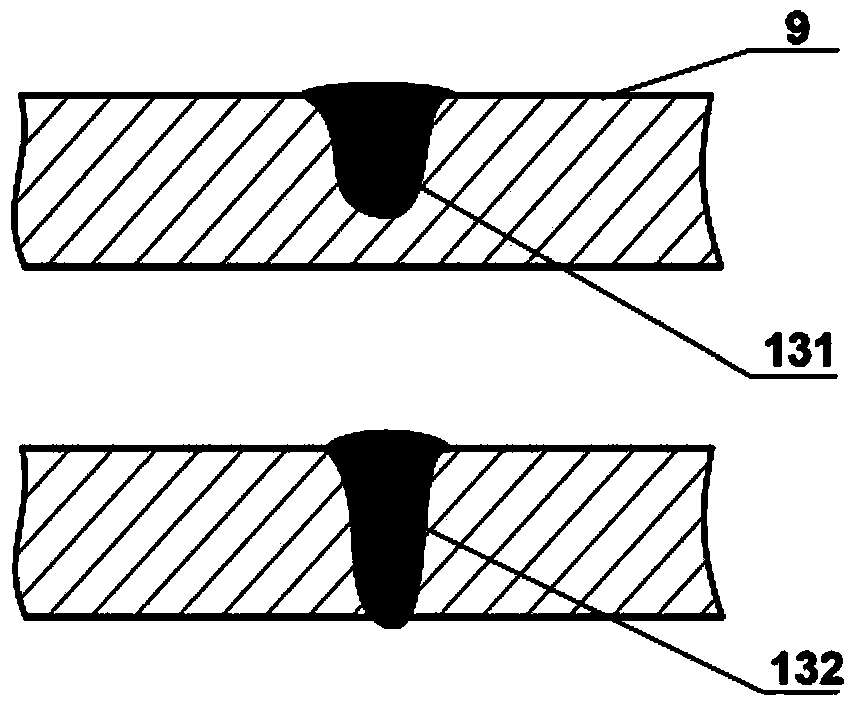
[0090] In this example, the welding workpiece 9 is a 6082 aluminum alloy flat plate structure with a plate thickness of 4 mm. The welding requirement is butt spot welding. The schematic diagram of the welding device is as follows: Figure 19 As shown in the figure, DISK solid-state laser and galvanometer scanning and focusing method are selected, the laser focal length is 350mm, the shape of the welding spot of the welding seam is a solid circle, and the cross-sectional feature is the form of full penetration.

[0091] The process parameters used in this example are: laser power 3500W, laser spot diameter 0.8mm, single point welding time 1s, laser beam swing along the radial direction 2mm, distance between electromagnetic conversion device and workpiece surface 4mm, pulse magnetic field induction intensity 120mT, Magnetic field pulse width 1s.

[0092] After the welding is completed, the obtained weld is beautiful in shape, free from defects such as center shrinkage, undercut ...


PUM

PropertyMeasurementUnit
poweraaaaaaaaaa
diameteraaaaaaaaaa
thicknessaaaaaaaaaa

Abstract

The invention discloses a hybrid welding method and hybrid welding equipment for laser electromagnetic pulse. The method can be used for laser seam welding and laser spot welding technology, a pulsed high magnetic field is applied to a welding region during the process of laser welding on a workpiece with the effect of laser beams so as to mutually react with an induced plasma, a welding pool and a stress strain field through welding and complete welding task. The equipment comprises a laser device, an electromagnetic pulse generator, a numerical control system, an optical transmission system and a laser electromagnetic pulse combined machining head. The combined machining head is used for integrating the laser beams with the pulsed high magnetic field and adjusting the distance between an electromagnetic conversion device and the workpiece; the combined machining head is arranged on a machine tool. The structural deformation can be reduced, the welding quality and machining efficiency are improved, and insurmountable technical problems when a metallic material structure is manufactured through existing single welding technology are solved.

Description

technical field [0001] The invention belongs to welding technology, in particular to a laser electromagnetic pulse composite welding method and equipment, which are especially suitable for laser electromagnetic pulse composite spot welding and seam welding of thin-walled metal materials. Background technique [0002] Welding is an important processing method for metal material structural parts, and it is widely used in the manufacturing fields of vehicles, aerospace, ships, buildings, bridges, and pressure vessels. Laser welding technology is a method of using a laser with high energy density as a heat source to heat and melt the workpiece to implement welding. It has the advantages of fast welding speed, small deformation, good joint quality, small heat affected zone, and is suitable for various metal materials. It is easy to realize. A series of advantages of automation, among which the laser seam welding and laser spot welding processes have become the focus of the curren...

Claims


Application Information

Patent Timeline
Patent Type & Authority Applications(China)
IPC IPC(8): B23K26/21B23K26/348B23K26/70
CPCB23K26/20B23K26/348B23K26/702
Inventor 高明曾晓雁李耿王磊张臣李祥友王泽敏
Owner 武汉飞能达激光技术有限公司
Why Eureka
Try Eureka