
Medium frequency pseudo noise geological radar

a geological radar and medium frequency technology, applied in the field of ground penetrating radar, can solve the problems of poor resolution, radar may be useless, and the frequency is too high to penetrate many lithologies of interes

Inactive Publication Date: 2002-08-22
ADMINISTATOR OF AERONAUTICS & SPACE ADMINISTATION U S GOVERNMENT AS REPRESENTED BY THE +1
View PDF0 Cites 35 Cited by
  • Summary
  • Abstract
  • Description
  • Claims
  • Application Information

AI Technical Summary

Benefits of technology

[0025] Another feature of a presently preferred embodiment of the invention is that a sampling speed of an analog to digital converter determines range measurement accuracy and range measurement resolution rather than the bandwidth of the system.
[0027] Yet another feature of one preferred embodiment of the present invention is a digital design that can be packaged and ruggedized to withstand the temperatures, pressures and size constraints of a down-hole environment.
[0028] An advantage of the present invention is the ability to map geological formation and fluid interfaces and track the movement of underground liquids such as in underground water reservoirs.
[0029] Yet another advantage of the present invention is the ability to produce very strong correlation peaks associated with long pseudo noise codes that can be used to discriminate against reflected signals from other ranges not currently being measured.
[0030] Yet another advantage of the present invention is great versatility and configurability to permit the same equipment to be used for a wide variety of applications.

Problems solved by technology

This frequency is too high to penetrate many lithologies of interest.
Range resolution is directly related to the bandwidth, thus the resolution becomes poor and the radar may be useless.
Another problem of the prior art is that multiple sensors or moving sensors are generally used for image forming and this is generally not possible or not practical at a subsurface location within a small diameter hole.
Such detectors are not generally useable for detection of downhole formation features and properties such as a water incursion many meters from the instrument because of a lack of sensitivity, poor resolution, and a weak response to water or other interfaces.
Another use of such a radar concerns a basic problem that has existed in the well logging business for decades, i.e., the effects of invasion that occur prior to running casing.
Because electronic logging tools are attempting to detect and measure the true formation fluids which have been displaced by an undetermined amount of drilling fluid, inaccuracies have, for decades, plagued the logging industry.
However, due to the unknown amount of change in resistivities, permittivities, electron densities, and so forth caused by the displacement of true formation fluid, and due to partial invasion regions wherein invasion is not complete, inaccuracies caused by invasion may be difficult to resolve.
The above prior art does not disclose a system that may be used in a borehole wherein operation may occur at medium frequencies and wherein resolution of formation features is not dependent upon system bandwidth.

Method used


Image

  • Medium frequency pseudo noise geological radar
  • Medium frequency pseudo noise geological radar
  • Medium frequency pseudo noise geological radar

Examples


Embodiment Construction

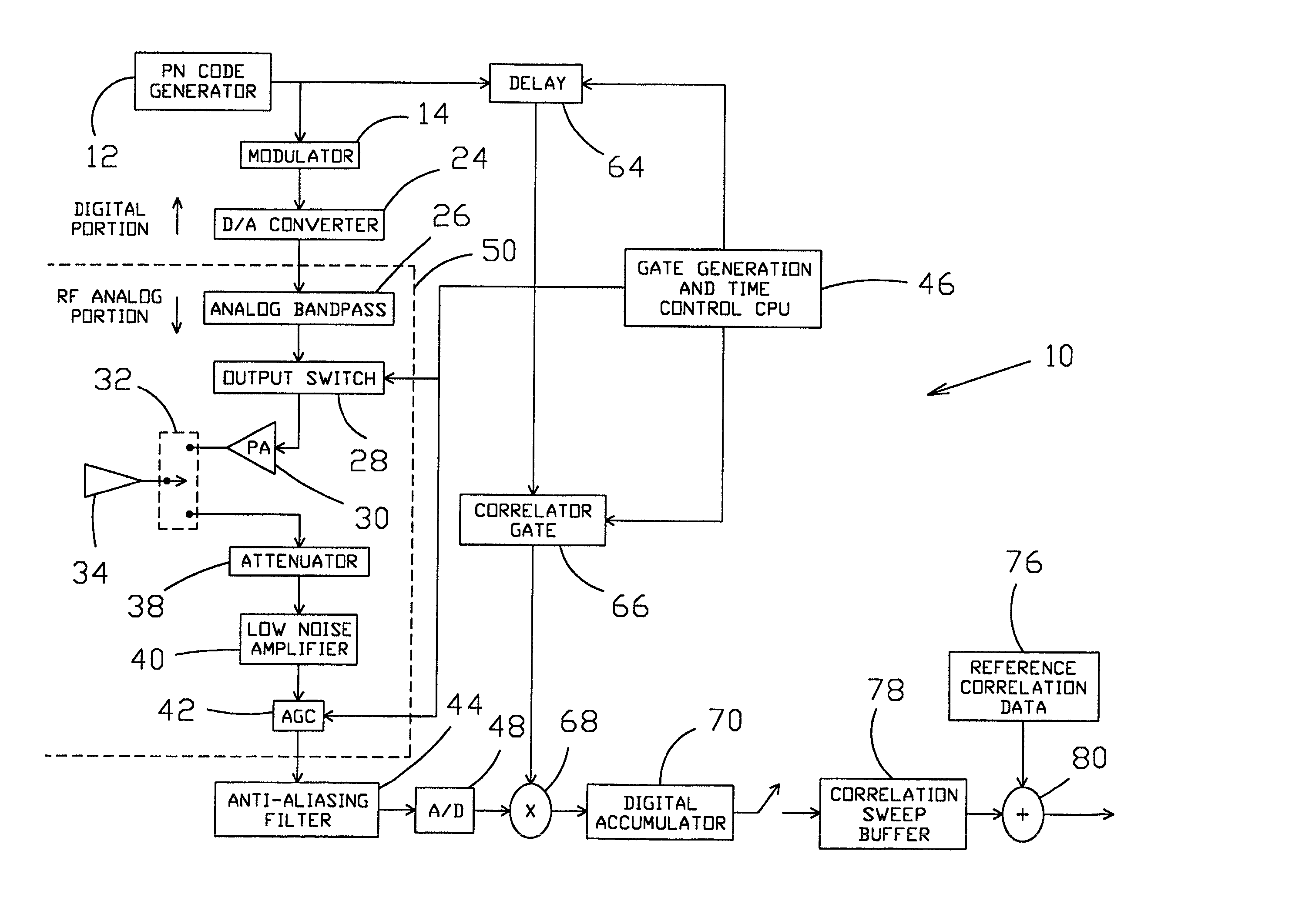
[0058] The present invention provides apparatus and methods for a ground penetrating radar with a pulsed pseudo noise code transceiver. Pseudo noise as referred to herein is a random recursive digital sequence, e.g., a random digital repeating sequence. When broadcast, the signal is spread over a wide range of frequencies so that at any particular frequency the signal may appear to be background noise or a pseudo noise.

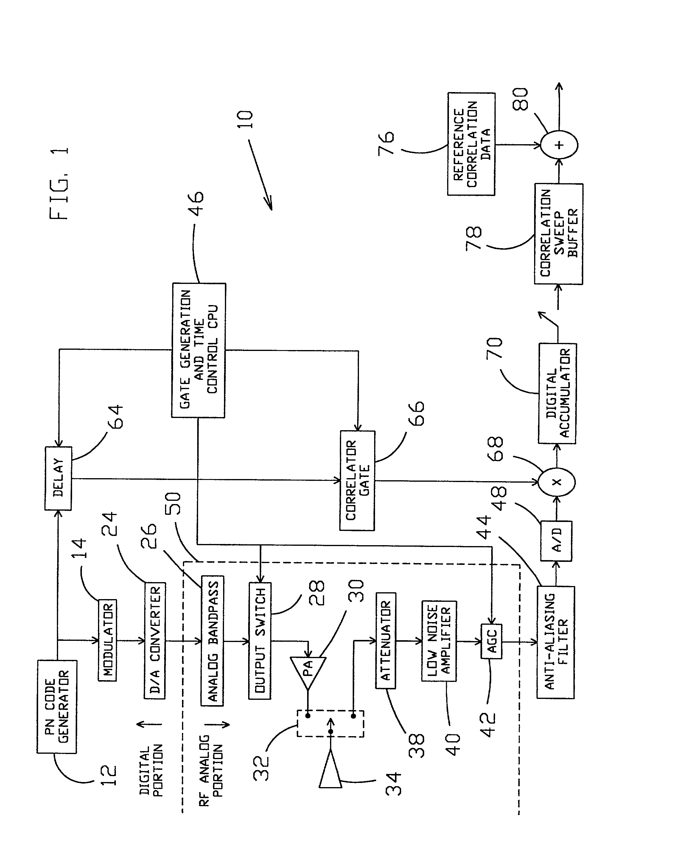
[0059] Referring now to the drawings, and more particularly to FIG. 1, there is shown a ground penetrating transceiver or georadar 10 in accord with the present invention. The use of an extremely long PN code, when needed, allows the generation of virtually unlimited transmission of energy thereby making detection of extremely low power reflections possible. Pseudo noise code generator 12 is used to create a sequence of code that is selectable in length. The length of the PN code is configurable depending upon how much processing gain is needed to extract the signal f...


PUM


Abstract

System and methods are disclosed for transmitting and receiving electromagnetic pulses through a geological formation. A preferably programmable transmitter having an all-digital portion in a preferred embodiment may be operated at frequencies below 1 MHz without loss of target resolution by transmitting and over sampling received long PN codes. A gated and stored portion of the received signal may be correlated with the PN code to determine distances of interfaces within the geological formation, such as the distance of a water interfaces from a wellbore. The received signal is oversampled preferably at rates such as five to fifty times as high as a carrier frequency. In one method of the invention, an oil well with multiple production zones may be kept in production by detecting an approaching water front in one of the production zones and shutting down that particular production zone thereby permitting the remaining production zones to continue operating.

Description

[0002] 1. Field of the Invention[0003] The present invention relates generally to ground penetrating radar and, more specifically, to a preferably digitally controlled transceiver operable to produce and broadcast a pseudo noise code through geological formations at medium frequencies.[0004] 2. Description of Prior Art[0005] Ground penetrating radars generally require a carrier frequency of at least 50 MHz in order to provide a useable range resolution. This frequency is too high to penetrate many lithologies of interest. If the carrier frequency is greatly reduced to permit better penetration of the medium, then the bandwidth of the radar must also be reduced. Range resolution is directly related to the bandwidth, thus the resolution becomes poor and the radar may be useless. It would be desirable to provide a system wherein resolution was not dependent on bandwidth so that lower frequency transmission could be used.[0006] Ground imaging radar systems also require system bandwidths...

Claims


Application Information

Patent Timeline
IPC IPC(8): G01S13/32G01S13/88G01V3/12
CPCG01S13/325G01S13/885G01V3/12Y02A90/30
Inventor ARNDT, G. DICKEYCARL, JAMES R.BYERLY, KENT A.AMINI, B. JON
Owner ADMINISTATOR OF AERONAUTICS & SPACE ADMINISTATION U S GOVERNMENT AS REPRESENTED BY THE
Learn More