
Optical sensor having fiduciary marks detected by Rayleigh scattered light

a technology of optical sensors and fiduciary marks, applied in the field of optical fibers, can solve the problems of limiting the reliability of rayleigh back scattering in distributed sensing applications, random spectral and spatial response of rayleigh back scattering, and additional problems

Active Publication Date: 2016-10-18
OFS FITEL LLC
View PDF1 Cites 9 Cited by
  • Summary
  • Abstract
  • Description
  • Claims
  • Application Information

AI Technical Summary

Problems solved by technology

Unfortunately, the spectral and spatial response of Rayleigh back scattering is random.
This limits the reliability of Rayleigh back scattering in distributed sensing applications.
If there is more than one core in the optical fiber, an additional problem arises.
However, the effective index and group index will not be the same in all cores of a multicore fiber.
Unfortunately, any drift in waveguide properties can render inaccurate any such calibration.
However, this technique requires the inscription of fiber gratings along the entire length of the fiber.
Such fabrication adds cost and complexity to a fiber sensor.

Method used


Image

  • Optical sensor having fiduciary marks detected by Rayleigh scattered light
  • Optical sensor having fiduciary marks detected by Rayleigh scattered light
  • Optical sensor having fiduciary marks detected by Rayleigh scattered light

Examples


Embodiment Construction

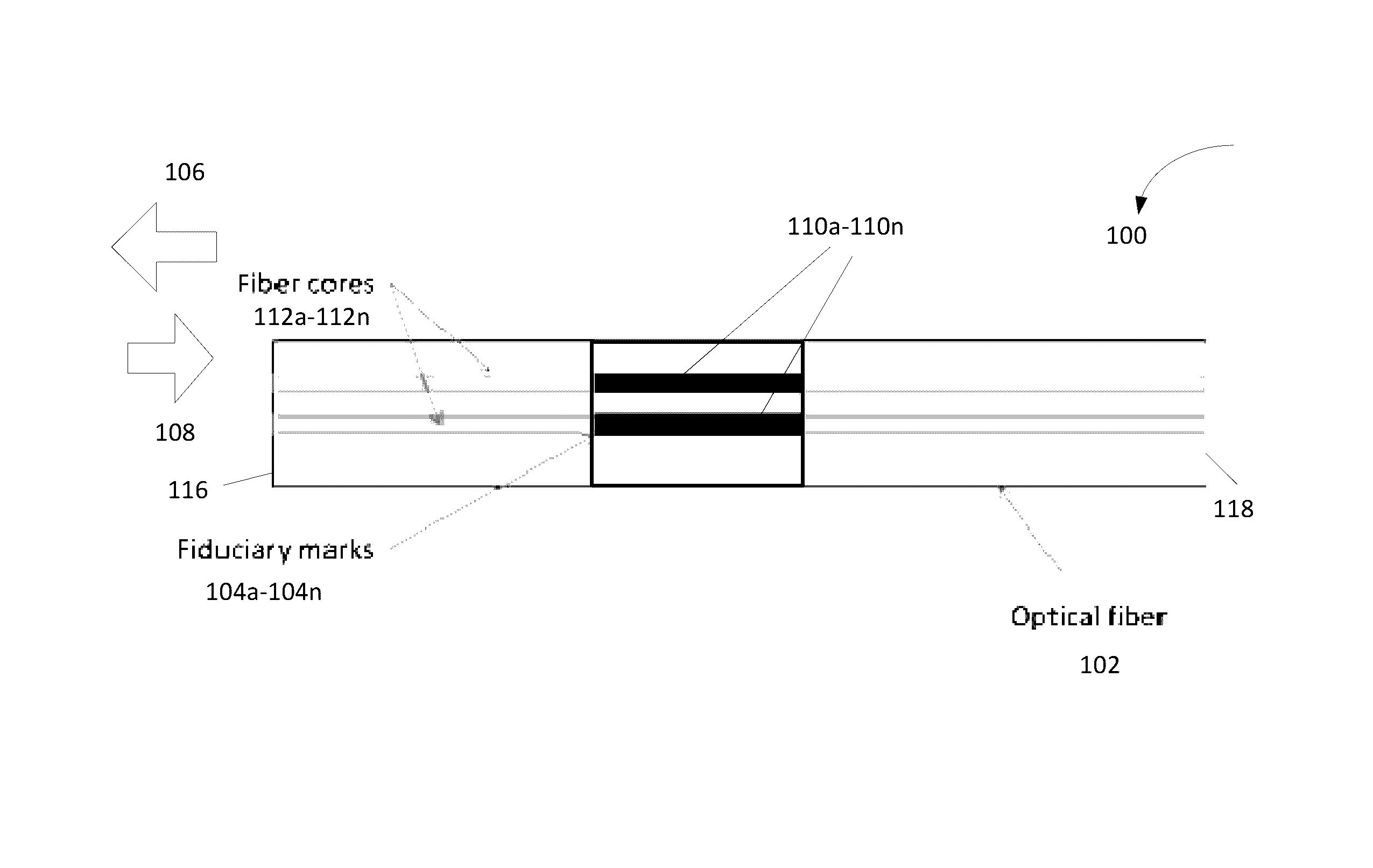
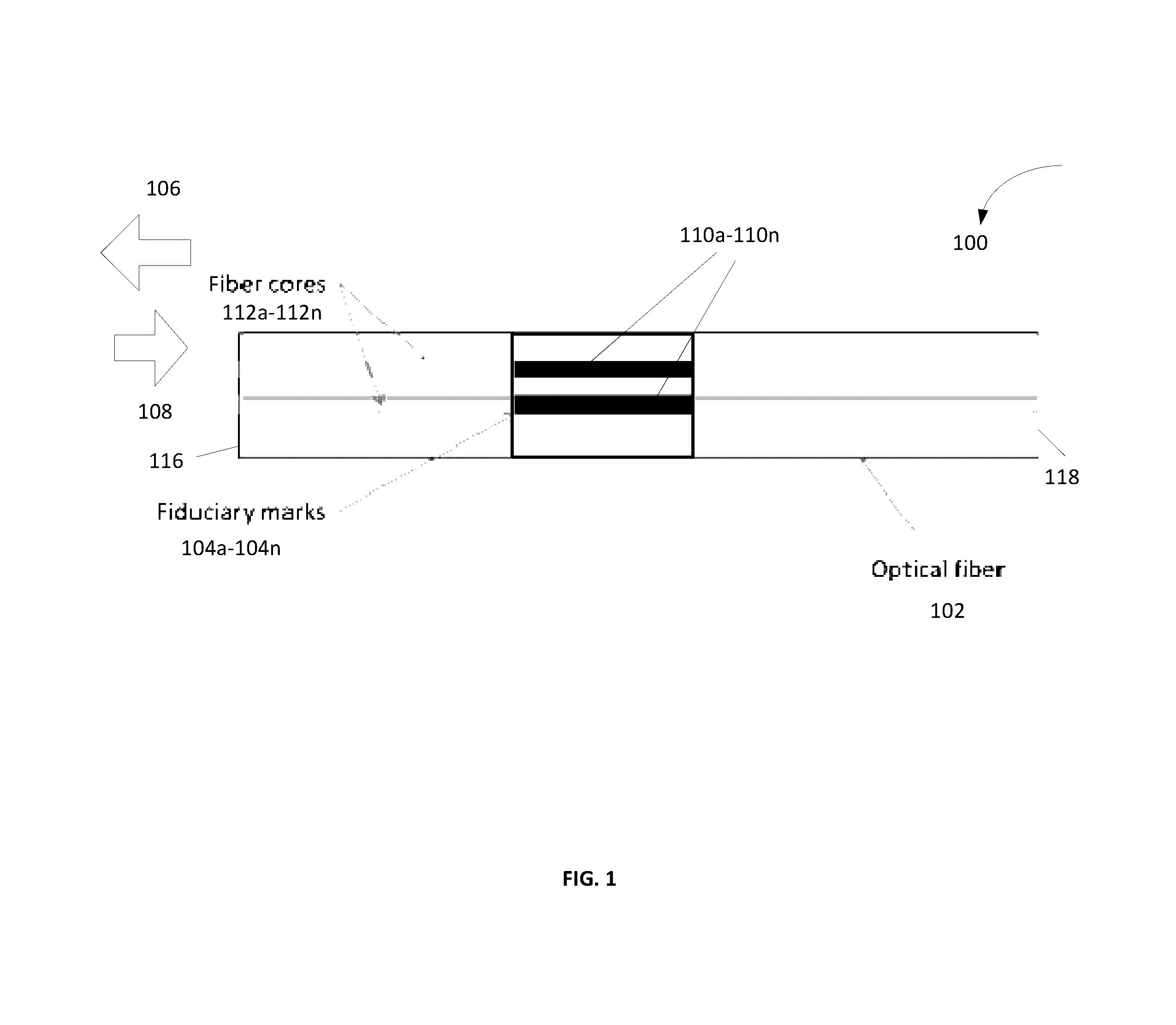
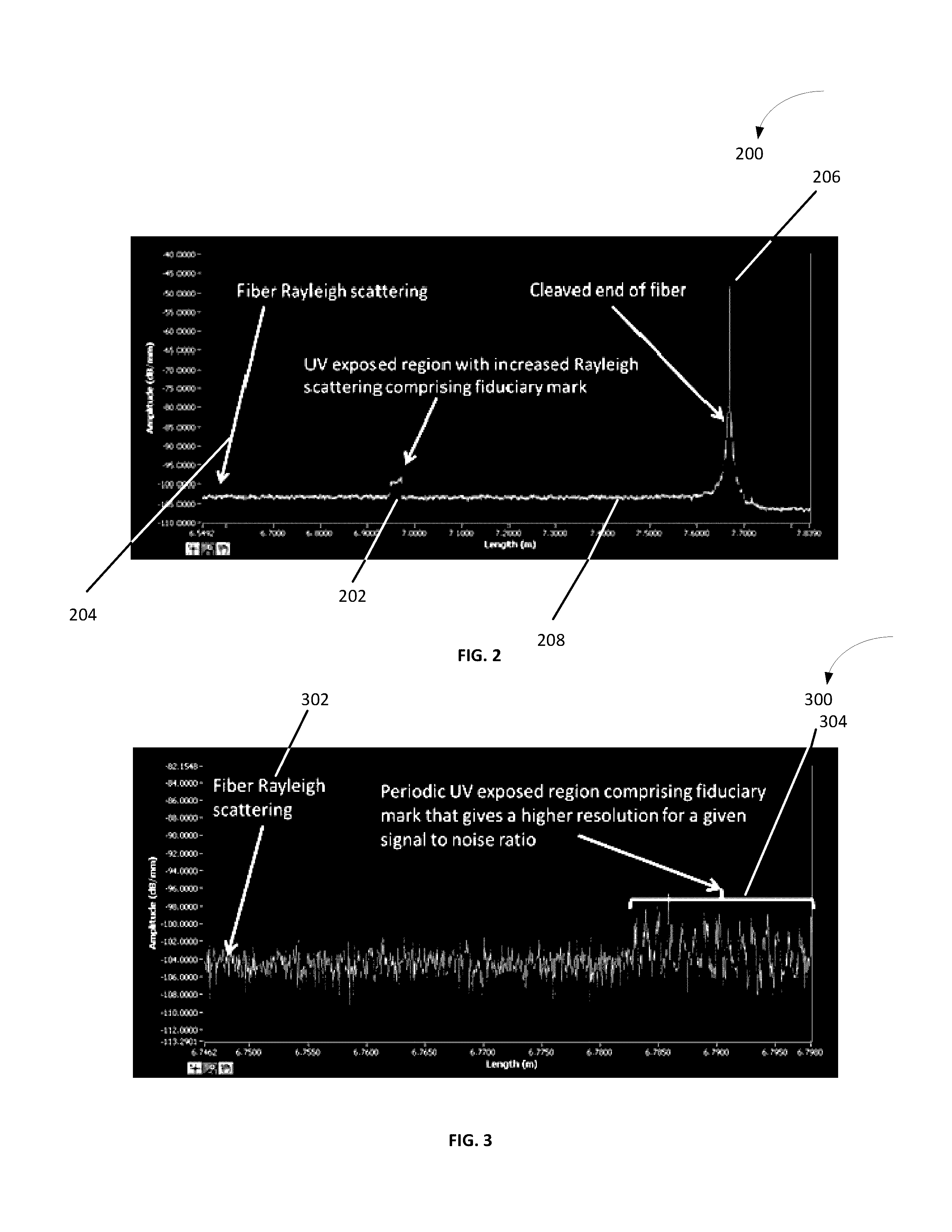
[0027]FIG. 1 is a perspective view of one embodiment of an optical sensor 100. The optical sensor 100 comprises an optical fiber 102 having at least one fiduciary mark 104a-104n. The at least one fiduciary mark 104a-104n is configured to produce an abrupt change in a Rayleigh backscattering signal 106 in the optical fiber 102 in response to an incoming signal / light 108. In one example, the at least one fiduciary mark 104a-104n is operable to change the amplitude and phase of a resulting Rayleigh scattering signal in an abrupt manner that appears clearly in a spatial trace of the Rayleigh back scattering response.

[0028]An abrupt change is defined as a change that occurs over a length of the optical fiber 102 that is on the order of, or less than, the spatial resolution of an interrogation system used to detect the Rayleigh back scattering response. This abrupt change may have an amplitude that is sufficiently large compared to fluctuations in a Rayleigh back scattering response signa...


PUM

PropertyMeasurementUnit
lengthaaaaaaaaaa
lengthaaaaaaaaaa
electricalaaaaaaaaaa

Abstract

An optical fiber having at least one fiduciary mark is provided. The at least one fiduciary mark is located at one or more axial positions along the optical fiber. The at least one fiduciary mark is configured to produce at least one change in a Rayleigh backscattering signal in the optical fiber. The at least one change in a Rayleigh backscattering signal may be an abrupt change in the Rayleigh backscattering signal. The abrupt change in the Rayleigh backscattering signal occurs over a length of the optical fiber that is of the order of or less than a spatial resolution of an interrogation system employed to detect the Rayleigh backscattering signal.

Description

CROSS-REFERENCE TO RELATED APPLICATIONS[0001]This application claims the benefit of U.S. provisional patent application No. 61 / 786,863 filed Mar. 15, 2013, the disclosure of which is incorporated herein by reference in its entirety.BACKGROUND OF THE INVENTION[0002]1. Field of the Invention[0003]The invention relates generally to optical fibers. More specifically, the invention relates to an optical sensor that employs Rayleigh backscattering to determine a location in the fiber sensor.[0004]2. Discussion of the Related Art[0005]Optical fibers have been employed in sensing applications, including measurements of distributed strain and temperature in an optical fiber. In one sensing application, an optical signal is transmitted into the optical fiber and perturbations in the fiber core(s) result in back scatter which may be analyzed to obtain the shape of the fiber.[0006]One type of back scattering that has been proposed for use in fiber shape measurements is Rayleigh back scattering....

Claims


Application Information

Patent Timeline
Patent Type & Authority Patents(United States)
IPC IPC(8): G01L1/24G01L1/00
CPCG01L1/242G01L1/00
Inventor WESTBROOK, PAUL S
Owner OFS FITEL LLC
Learn More