
Light-emitting device

a technology of light-emitting devices and phosphors, which is applied in the direction of fixed installations, lighting and heating apparatus, instruments, etc., can solve the problems of decreasing the intensity of the fluorescence emitted from the phosphor layer excited by the excitation light, the intensity of the excitation light on the phosphor layer is not uniform, and the intensity of the fluorescence emitted from the phosphor layer is also not uniform, so as to improve the uniformity of the fluorescen

Active Publication Date: 2016-10-18
SHARP FUKUYAMA LASER CO LTD
View PDF35 Cites 4 Cited by
  • Summary
  • Abstract
  • Description
  • Claims
  • Application Information

AI Technical Summary

Benefits of technology

[0007]In view of the above-described problems, the present disclosure provides a light-emitting device capable of improving the uniformity of the brightness distribution of the fluorescence.

Problems solved by technology

However, in the light source device according to Japanese Unexamined Patent Application Publication No. 2012-89316, the intensity of the excitation light on the phosphor layer is not uniform.
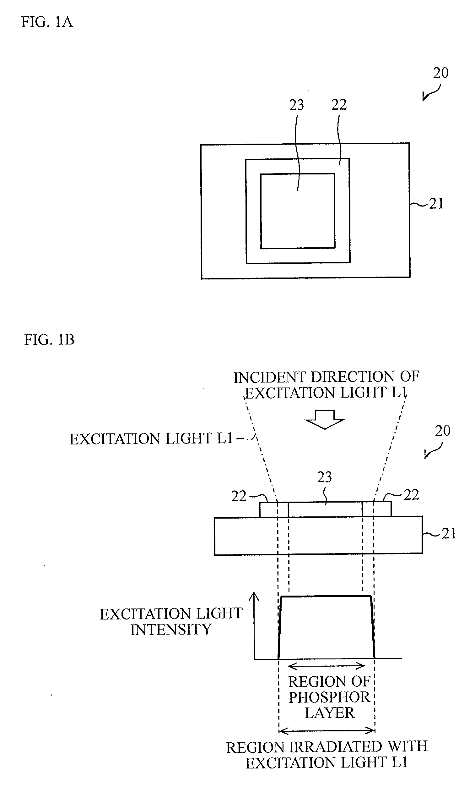
Firstly, in the case where the intensity of the excitation light on the phosphor layer is not uniform, the intensity of the fluorescence emitted from the phosphor layer excited by the excitation light is also not uniform. Therefore, fluorescence having a nonuniform brightness distribution is emitted from the phosphor layer.
Secondly, the phosphor layer receives a large amount of energy from the excitation light in a region where the intensity of the excitation light incident on the phosphor layer is the highest, and the temperature becomes high in that region as a result. Accordingly, temperature quenching and / or deterioration of the phosphor occur in that region, and the intensity of the fluorescence emitted from the phosphor decreases. As a result, the brightness distribution of the fluorescence emitted from the phosphor layer becomes nonuniform. Lastly, when the position of incidence of the excitation light on the phosphor layer is displaced or shifted, the intensity distribution of the fluorescence on the phosphor layer changes. In such a case, the intensity distribution and the shape of the fluorescence emitted to the outside from the light source device also change. This also makes the brightness distribution of the fluorescence nonuniform.

Method used


Image

  • Light-emitting device
  • Light-emitting device
  • Light-emitting device

Examples


second embodiment

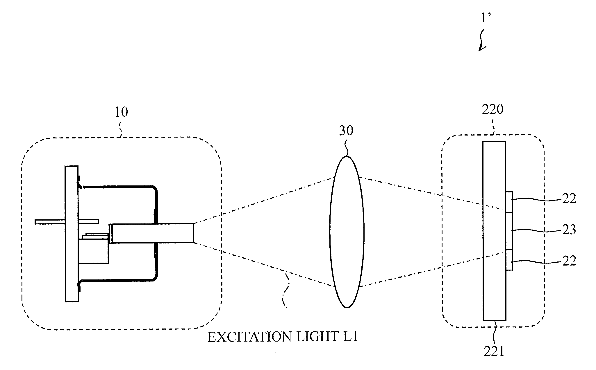
[0062]the present disclosure will now be described with reference to FIG. 4. For convenience of description, components having the same functions as those described in the above-described embodiment are denoted by the same reference numerals, and descriptions thereof are thus omitted.

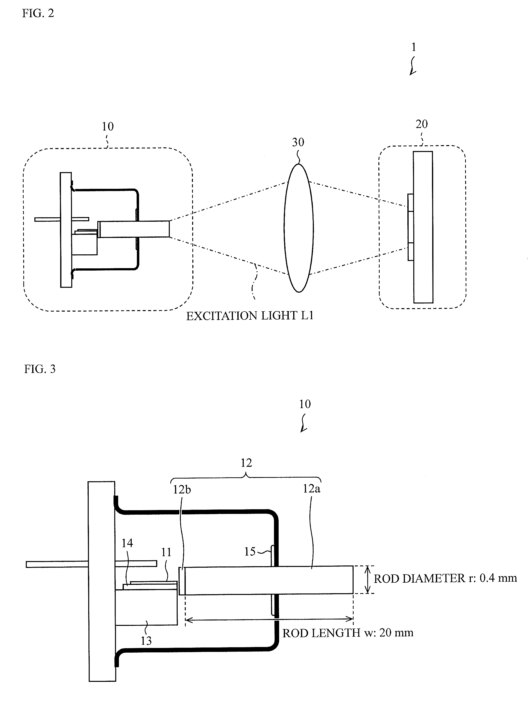
[0063]In the light-emitting device 1 according to the above-described embodiment, the surface of the phosphor layer 23 on which the excitation light L1 is incident is the same as the surface of the phosphor layer 23 from which the fluorescence is emitted (see FIG. 2).

[0064]In contrast, as illustrated in FIG. 4, a light-emitting device 1′ according to the present embodiment is structured such that a surface of a phosphor layer 23 on which excitation light L1 is incident (back surface) and a surface of the phosphor layer 23 from which fluorescence is emitted (front surface) are at opposite sides. In the light-emitting device 1′, fluorescence emitted from a surface (front surface) at a side opposite to a s...

third embodiment

[0067]the present disclosure will now be described with reference to FIGS. 5A to 5C. For convenience of description, components having the same functions as those described in the above-described embodiments are denoted by the same reference numerals, and descriptions thereof are thus omitted.

first embodiment

[0068]A light-emitting device 1 according to the present embodiment includes a light-emitting unit 320 instead of the light-emitting unit 20 in the structure illustrated in FIG. 2. In addition, a laser unit 10 emits excitation light L1 having a wavelength of about 450 nm. Other structures are the same as those in the

[0069]The structure of the light-emitting unit 320 will now be described with reference to FIG. 5A. FIG. 5A is a sectional view of the light-emitting unit 320. As illustrated in FIG. 5A, the light-emitting unit 320 includes a reflective substrate 21, an absorber (light-emitting-region defining portion, blocking portion) 324, and a phosphor layer 323.

[0070]The absorber 324 absorbs the excitation light L1 and fluorescence. The absorber 324 is formed so as to cover the entire areas of the side surfaces of the phosphor layer 323. Therefore, a portion of the excitation light L1 that is incident on the light-emitting unit 320 at a position deviated from the top surface of the ...


PUM


Abstract

A light-emitting device includes a light-emitting portion that emits fluorescence in response to excitation light incident on a surface of the light-emitting portion, and a reflector that defines a light-emitting region on the surface of the light-emitting portion, the fluorescence being emitted from the light-emitting region. The excitation light has a top-hat energy intensity distribution on the surface of the light-emitting portion.

Description

CROSS-REFERENCE TO RELATED APPLICATION[0001]The present disclosure contains subject matter related to that disclosed in Japanese Priority Patent Application JP 2013-127871 filed in the Japan Patent Office on Jun. 18, 2013, the entire contents of which are hereby incorporated by reference.FIELD OF THE INVENTION[0002]The present disclosure relates to a light-emitting device including an excitation light source that emits excitation light and a light-emitting unit that emits fluorescence in response to the excitation light.BACKGROUND OF THE INVENTION[0003]Light-emitting devices including an excitation light source that emits excitation light and a light-emitting unit that emits fluorescence in response to the excitation light have been developed.[0004]An example of a light-emitting device is a light source device described in Japanese Unexamined Patent Application Publication No. 2012-89316 (published May 10, 2012). The light source device includes a solid light source that emits excit...

Claims


Application Information

Patent Timeline
Patent Type & Authority Patents(United States)
IPC IPC(8): G02B27/09F21K99/00F21S8/10
CPCG02B27/0994F21K9/64F21K9/61F21S48/1145F21Y2101/00G02B27/0927F21V13/14F21Y2115/10F21S41/16F21S41/176F21S45/47F21S41/24F21S41/285F21S41/39F21V7/26F21V9/40F21Y2115/30H01S5/0064
Inventor SAKAUE, TOMOHIROTAKAHASHI, KOJITAKAHIRA, YOSHIYUKIMAEMURA, YOSUKE
Owner SHARP FUKUYAMA LASER CO LTD
Learn More