
Universal teletherapy treatment room arrangement

a technology of treatment room and teletherapy, applied in the field ofteletherapy, can solve the problems of limiting the number of available proton therapy centers, prohibitively expensive structure, and minimal safe use of deeply embedded growths

Active Publication Date: 2016-10-25
P CURE
View PDF7 Cites 3 Cited by
  • Summary
  • Abstract
  • Description
  • Claims
  • Application Information

AI Technical Summary

Benefits of technology

The present invention provides a teletherapy treatment arrangement that overcomes the disadvantages of prior art methods and arrangements. The arrangement includes a 3 dimensional imager and at least one 2 dimensional imager that provide a pair of 2 dimensional images along planes generally orthogonal to the effective patient plane of the 3 dimensional imager. The arrangement also includes a patient positioner that can secure the patient target tissue in a fixed spatial relationship to the patient positioner. The control unit can input the planned treatment position of the patient target tissue and obtain position information of the patient target tissue from the 3 dimensional imager or the at least one 2 dimensional imager. The arrangement can provide volumetric information of the patient target tissue and allow for free motion of the patient in relation to the treatment position. The arrangement can be provided in a treatment room with walls and an irradiation source. The technical effects of the invention include improved precision and accuracy of treatment positioning, improved target tissue imaging, and improved patient comfort.

Problems solved by technology

Unfortunately, X-rays exhibit a linear energy transfer approaching an exponential attenuation function, and are therefore of minimal safe use for deeply embedded growths.
As a result of this effect, increased energy can be directed at an embedded growth as compared to X-rays and electron beams, which particularly harm intervening tissues.
Unfortunately, the beam generating and delivery system is extremely heavy, and the need for such a gantry system leads to a prohibitively expensive structure limiting the number of available proton therapy centers.
Such a system is limited to a patient being treated in a supine position, thus requiring a costly gantry based irradiation system.
Such an imager adds cost to each treatment room, since commercially available imagers are primarily arranged to image patients in a fixed, predetermined position, generally horizontal.
Such an apparatus is ideal for vertical translation, however is not particularly appropriate for generally horizontal patient treatment positions.

Method used


Image

  • Universal teletherapy treatment room arrangement
  • Universal teletherapy treatment room arrangement
  • Universal teletherapy treatment room arrangement

Examples


Embodiment Construction

[0040]Before explaining at least one embodiment of the invention in detail, it is to be understood that the invention is not limited in its application to the details of construction and the arrangement of the components set forth in the following description or illustrated in the drawings. The invention is applicable to other embodiments or of being practiced or carried out in various ways. Also, it is to be understood that the phraseology and terminology employed herein is for the purpose of description and should not be regarded as limiting.

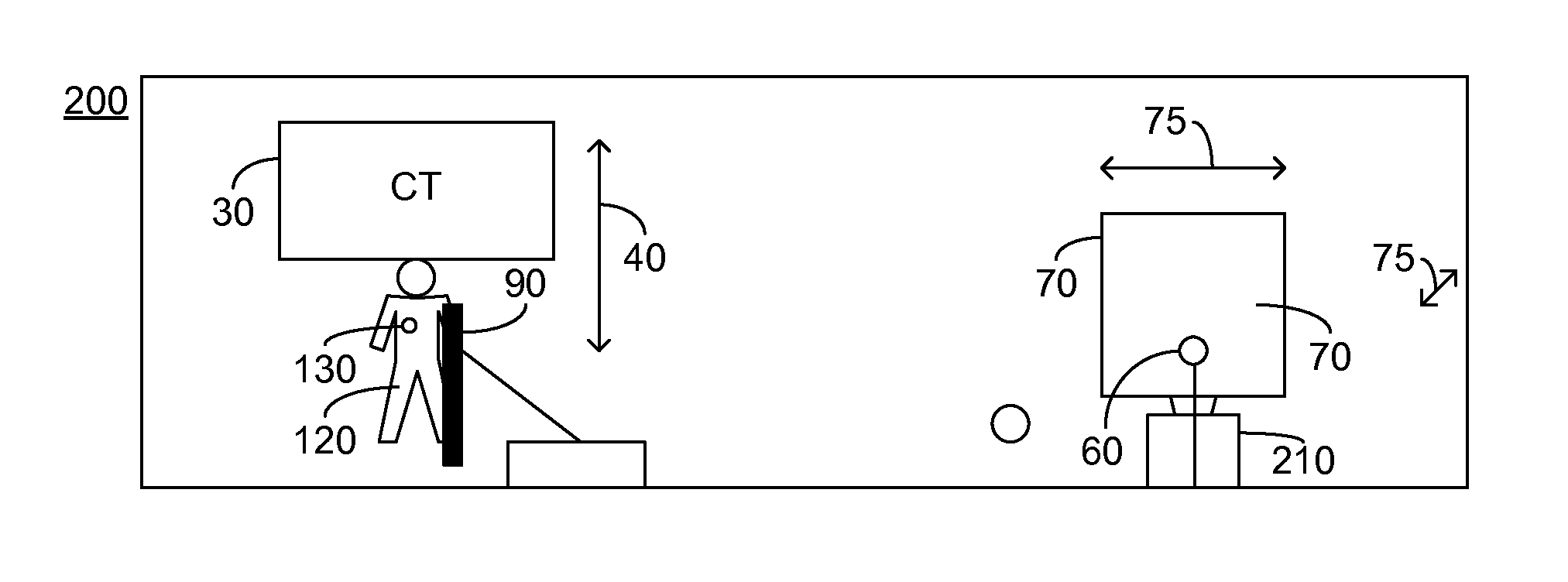
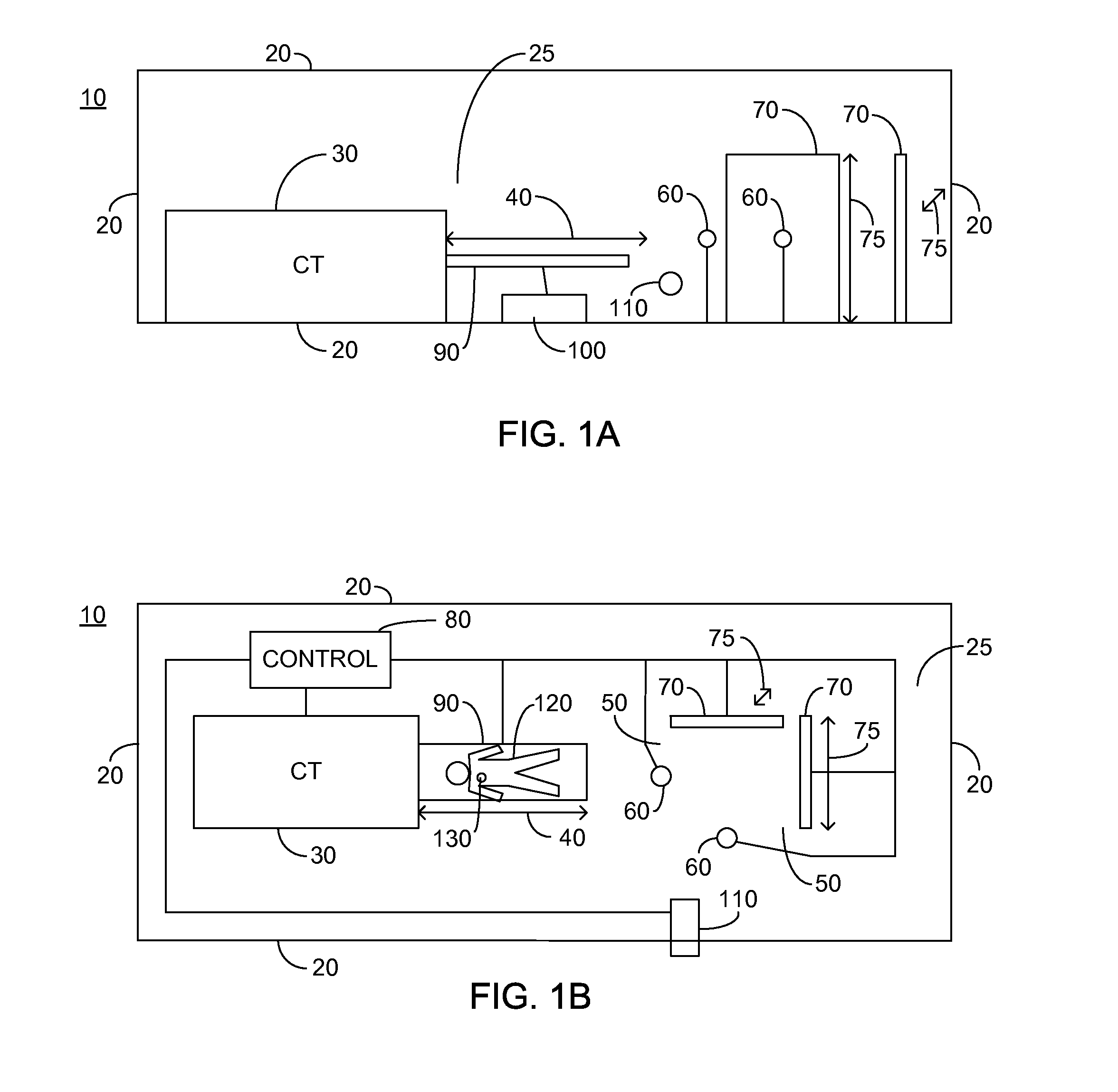
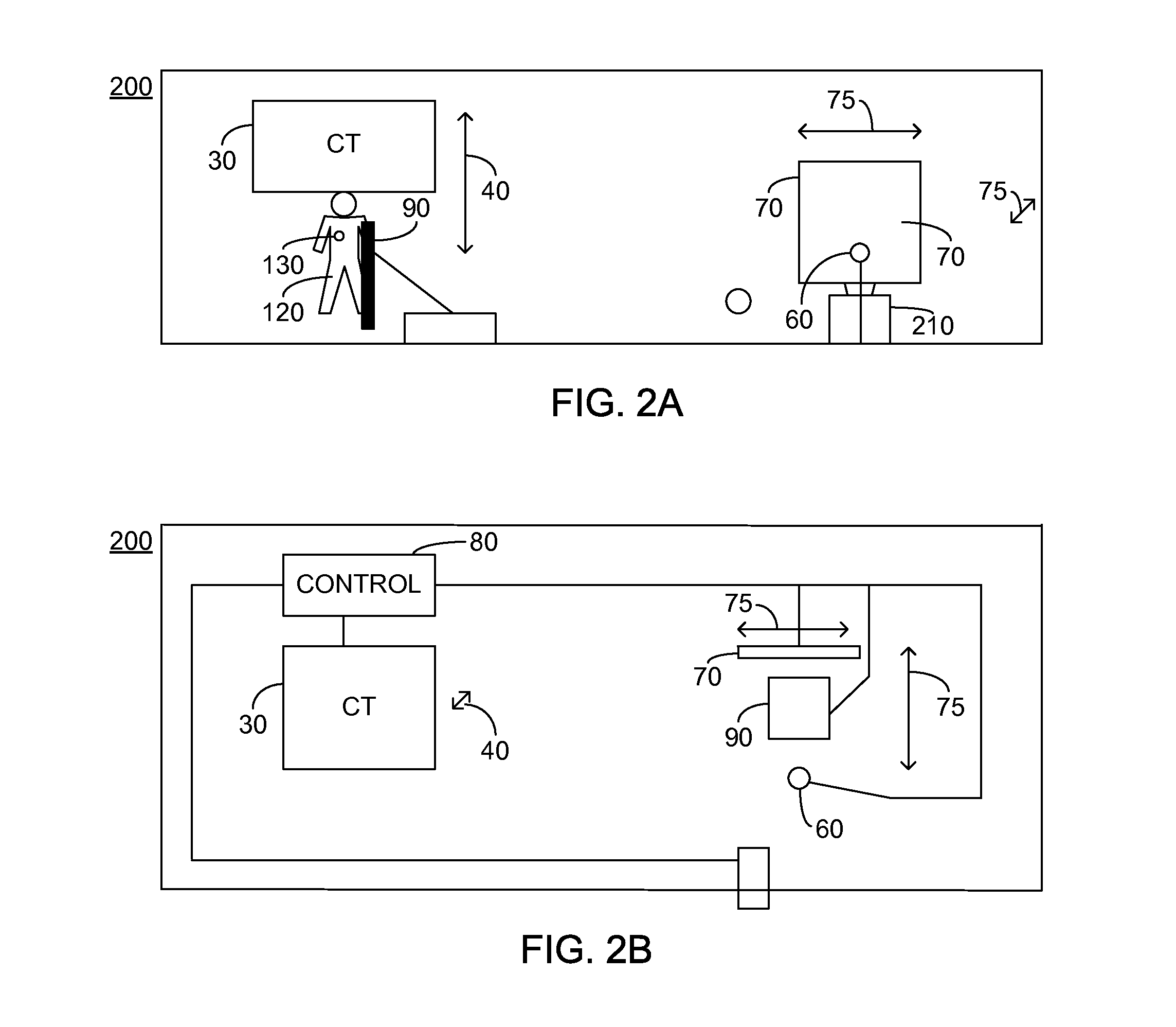
[0041]FIG. 1A illustrates a high level side view of an exemplary embodiment of a teletherapy treatment arrangement 10 and FIG. 1B illustrates a high level top view of teletherapy treatment arrangement 10, the description of FIGS. 1A and 1B being taken together. Teletherapy treatment arrangement 10 comprises: a plurality of generally linear surfaces 20 defining a treatment room 25, with generally linear surfaces 20 comprising walls, floor and a...


PUM


Abstract

A teletherapy treatment arrangement constituted of: a control unit; a 3 dimensional imager having an effective patient plane; at least one 2 dimensional imager arranged to provide a pair of 2 dimensional images along planes generally orthogonal to the effective patient plane of the 3 dimensional imager; and a patient positioner arranged to secure a target tissue in a fixed relationship to the patient positioner, the control unit arranged to: input a planned treatment position of the patient target tissue; in the event that the planned treatment position is consonant with the effective patient plane of the 3 dimensional imager, obtain position information of the target tissue from the 3 dimensional imager, and in the event that the planned treatment position is not consonant with the effective patient plane of the 3 dimensional imager, obtain position information of the target tissue from the at least one 2 dimensional imager.

Description

CROSS-REFERENCE TO RELATED APPLICATIONS[0001]This application claims priority from: U.S. Provisional Patent Application Ser. No. 61 / 481,205 filed May 1, 2011 entitled “Universal Teletherapy Treatment Room Arrangement”, the entire contents of which are incorporated herein by reference.TECHNICAL FIELD[0002]The present disclosure relates generally to the field of teletherapy and in particular to a teletherapy treatment room arrangement comprising: a 3 dimensional imager; and a pair of 2 dimensional imagers arranged along planes orthogonal to the primary imaging plane of the 3 dimensional imager.BACKGROUND OF THE INVENTION[0003]Teletherapy is defined as a treatment methodology in which an irradiation source is at a distance from the body to be treated. X-rays and electron beams have long been used in teletherapy to treat various cancers. Unfortunately, X-rays exhibit a linear energy transfer approaching an exponential attenuation function, and are therefore of minimal safe use for deepl...

Claims


Application Information

Patent Timeline
Patent Type & Authority Patents(United States)
IPC IPC(8): A61B6/03A61N5/10A61B6/00A61B6/04
CPCA61N5/103A61B6/03A61B6/032A61B6/04A61B6/0492A61B6/5235A61B6/5247A61N5/1049A61N2005/1061
Inventor MARASH, MICHAEL
Owner P CURE
Learn More