
Liquid ejecting head and liquid ejecting apparatus

a liquid ejector and liquid ejector technology, applied in printing and other directions, can solve the problems of limiting the displacement of piezoelectric vibrators and unfavorably affecting ink discharge characteristics, and achieve the effect of enhancing the displacement amount of piezoelectric vibrators and enhancing the discharge characteristi

Active Publication Date: 2016-11-01
SEIKO EPSON CORP
View PDF7 Cites 2 Cited by
  • Summary
  • Abstract
  • Description
  • Claims
  • Application Information

AI Technical Summary

Benefits of technology

[0012]An advantage of some aspects of the invention is to provide a liquid ejecting head capable of enhancing an amount of displacement of a piezoelectric vibrator and enhancing a discharge characteristic using the piezoelectric vibrator, and a liquid ejecting apparatus.
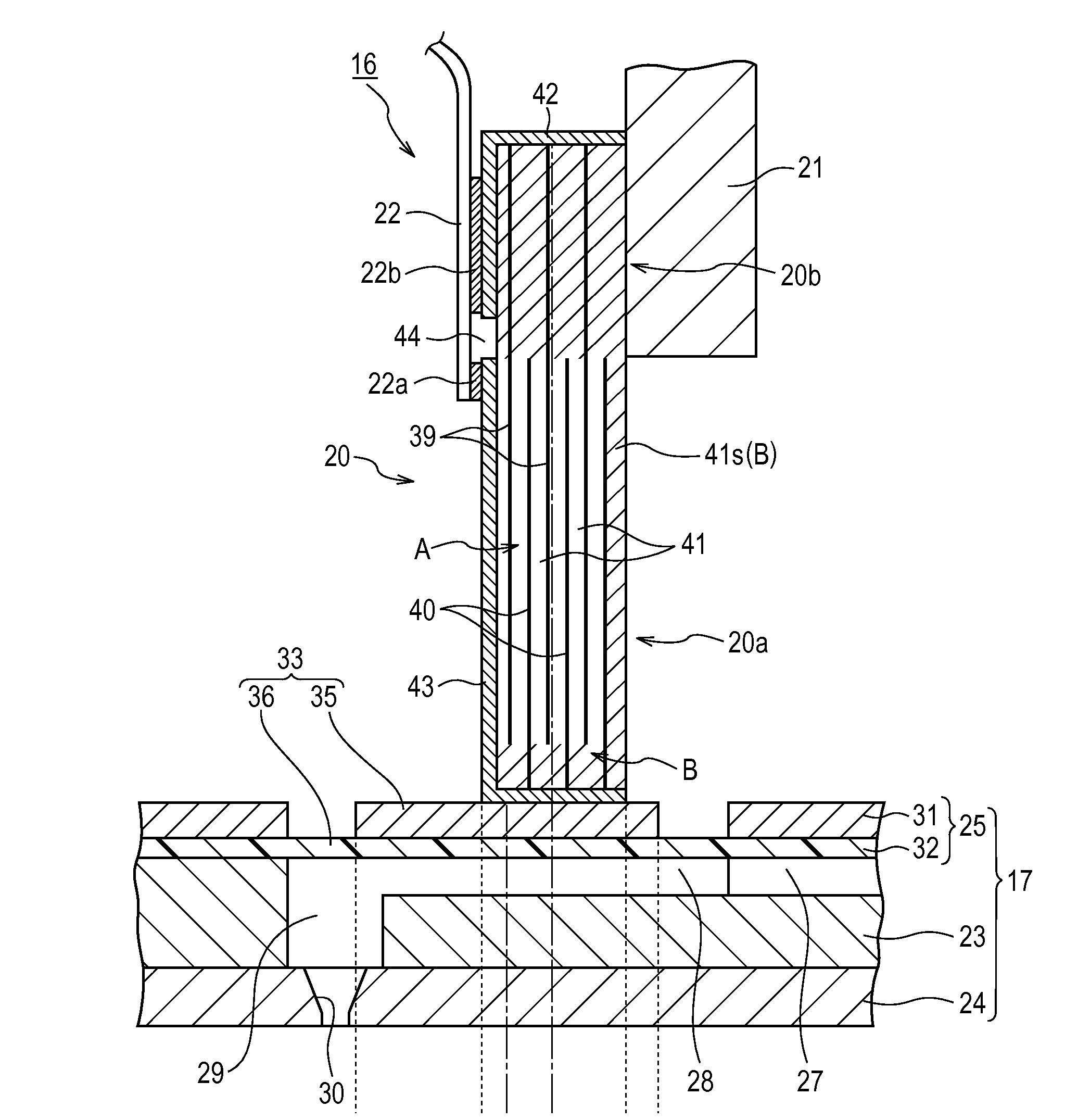
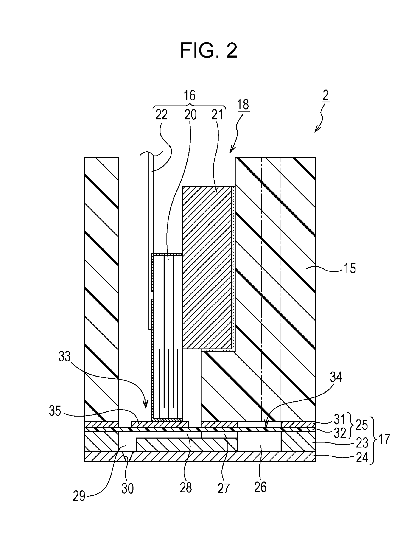
[0014]By employing the configuration in which an electrode is formed on a layer at the end of the first side of the laminate structure in the laminating direction while no electrode is formed on a layer at the end of the second side thereof in the laminating direction, it is possible to make the displacement amount of the layer at the end of the first side be large and also make the displacement amount be larger for sure than the displacement amount of the layer at the end of the second side. In comparison with a case in which electrodes are formed on layers on both ends of the first and second sides, a magnitude relationship of the displacement amounts from the layer at the end of the second side toward the layer at the end of the first side, that is, a magnitude relationship that the displacement amount becomes larger as it progresses from the layer at the end of the second side toward the layer at the end of the first side, is always maintained between individual piezoelectric vibrators and also between the ends of the first side and the second side of the identical piezoelectric vibrator. Further, because the piezoelectric vibrator is disposed so as to be shifted toward the second side in the laminating direction with respect to the effective displacement portion, it is possible to displace the regions on both sides from the center of the effective displacement portion in the laminating direction as equally as possible when the piezoelectric vibrator is driven. As a result, the displacement of the piezoelectric vibrator at the time of being driven can be further effectively converted to a pressure change. Furthermore, since the volume of the pressure chamber can be changed efficiently and stably by driving the piezoelectric vibrator, it is possible to reduce problems such as variation in a liquid amount ejected through the nozzle, variation in the flying direction of the liquid, and the like caused by deflection in the displacement of the piezoelectric vibrator.
[0017]According to the above configuration, a portion on the first side of the piezoelectric vibrator whose displacement amount is relatively large is disposed on a portion of the island-shaped part whose width is relatively small, while a portion on the second side of the piezoelectric vibrator whose displacement amount is relatively small is disposed on a portion of the island-shaped part whose width is relatively wide. Further, in a wide-width portion where the width of the island-shaped part is wider, a larger area range of the effective displacement portion is displaced in comparison with a case of a narrow-width portion where the width of the island-shaped part is narrower. Accordingly, it is possible to make the displacement amounts of the regions on both sides from the center of the effective displacement portion in the laminating direction be further matched when the piezoelectric vibrator is driven. As a result, the volume of the pressure chamber can be further effectively and stably changed.
[0019]According to this configuration, it is possible to efficiently convert the displacement of the piezoelectric vibrator to a change in volume of the pressure chamber.
[0022]According to the above configuration, by employing the configuration in which an electrode is formed on the layer at the end of the third side of the laminate structure in the laminating direction while no electrode is formed on the layer at the end of the second side of the laminate structure in the same direction, it is possible to make the displacement amount of the layer at the end of the third side be large and also make the displacement amount be larger for sure than the displacement amount of the layer at the end of the fourth side. In comparison with a case in which electrodes are formed on layers at both ends of the third and fourth sides, a magnitude relationship of the displacement amounts from the layer at the end of the fourth side toward the layer at the end of the third side, that is, a magnitude relationship that the displacement amount becomes larger as it progresses from the layer at the end of the fourth side toward the layer at the end of the third side, is always maintained between individual piezoelectric vibrators and also between the ends of the third side and the fourth side of the identical piezoelectric vibrator. Further, because the island-shaped part is provided so as to be shifted toward the fourth side in the laminating direction with respect to the effective displacement portion, it is possible to displace the regions on both sides from the center of the effective displacement portion in the laminating direction as equally as possible via the island-shaped part when the piezoelectric vibrator is driven. As a result, the displacement of the piezoelectric vibrator at the time of being driven can be further effectively converted to a pressure change. Furthermore, since the volume of the pressure chamber can be changed efficiently and stably by driving the piezoelectric vibrator, it is possible to reduce problems such as variation in a liquid amount ejected through the nozzle, variation in the flying direction of the liquid, and the like caused by deflection in the displacement of the piezoelectric vibrator.

Problems solved by technology

In JP-A-2001-347660, a problem is described that a fixing plate which is bonded to a base end portion on one side surface in a laminating direction of the piezoelectric layers and electrodes limits the displacement of the piezoelectric vibrator.
The variation in the thickness causes a variation in the active displacement of the corresponding portions of the piezoelectric vibrator, which in turn unfavorably influences an ink discharge characteristic.
The above problem occurs not only in an ink jet recording apparatus equipped with an ink jet recording head for discharging ink, but also in a liquid ejecting apparatus equipped with a different liquid ejecting head for ejecting a liquid other than ink.

Method used


Image

  • Liquid ejecting head and liquid ejecting apparatus
  • Liquid ejecting head and liquid ejecting apparatus
  • Liquid ejecting head and liquid ejecting apparatus

Examples


Embodiment Construction

[0035]Hereinafter, embodiments for implementing the present invention will be described with reference to the accompanying drawings. Although various features are placed in the embodiments described below as preferred examples of the present invention, the scope of the present invention is not limited thereto. Note that in the following embodiments, as a liquid ejecting apparatus of the present invention, an ink jet recording apparatus (hereinafter, called a “printer”) equipped with an ink jet recording head (hereinafter, called a “recording head”), which is a type of a liquid ejecting head, is cited and explained.

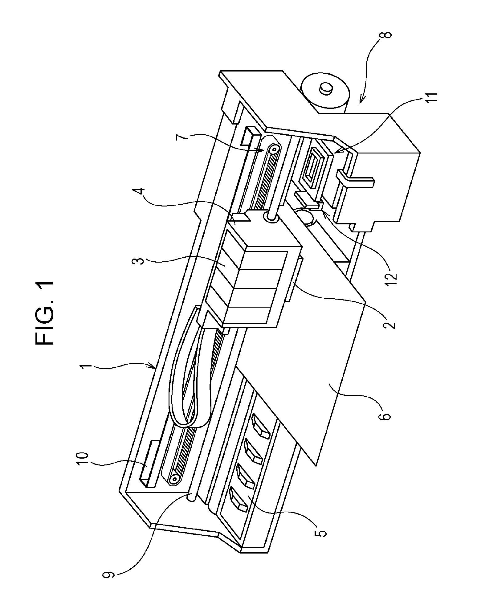
[0036]FIG. 1 is a view illustrating a configuration of a printer 1. The printer 1 is generally configured of a carriage 4 on which a recording head 2 is mounted and an ink cartridge 3, which is a type of a liquid supply source, is also mounted in a detachable manner, a platen 5 disposed under the recording head 2 in recording operation, a carriage movement mechanism 7 conf...


PUM


Abstract

In a liquid ejecting head, a vibration plate includes an effective displacement portion provided for each pressure chamber and an island-shaped part which is provided in the effective displacement portion at a position on the opposite side to the pressure chamber and to which one end portion of a piezoelectric vibrator is bonded; the piezoelectric vibrator has a laminate structure in which electrodes and piezoelectric material are alternately laminated; a layer at an end of one side of the piezoelectric vibrator in the laminating direction is formed of an external electrode, while a layer at an end of the other side thereof in the same direction is formed of a piezoelectric material; and the piezoelectric vibrator is disposed so as to be shifted toward the other side in the laminating direction with respect to the effective displacement portion.

Description

RELATED APPLICATION[0001]This application claims the benefit of U.S. Provisional Application No. 61 / 863,551 filed on Aug. 8, 2013. The entire disclosure of the above application is incorporated herein by reference.BACKGROUND[0002]1. Technical Field[0003]The present invention relates to liquid ejecting heads such as ink jet recording heads and liquid ejecting apparatuses, and particularly relates to liquid ejecting heads that eject liquid through a nozzle by displacing a diaphragm portion defining part of a pressure chamber using a piezoelectric element, and liquid ejecting apparatuses.[0004]2. Related Art[0005]Liquid ejecting apparatuses are apparatuses that include a liquid ejecting head capable of ejecting liquid as a liquid droplet and eject various kinds of liquids from the liquid ejecting head. As a representative example of liquid ejecting apparatuses, an image recording apparatus such as an ink jet recording apparatus (printer) that includes an ink jet recording head (hereina...

Claims


Application Information

Patent Timeline
Patent Type & Authority Patents(United States)
IPC IPC(8): B41J2/045B41J2/14
CPCB41J2/04581B41J2/04588B41J2/14274
Inventor TOGASHI, ISAMU
Owner SEIKO EPSON CORP
Learn More