Conductive terminal

a technology of conductive terminals and terminals, applied in the direction of coupling device connections, electrical apparatus, live contact access prevention, etc., can solve problems such as damage to fixing members, and achieve the effect of uniform clamping

Active Publication Date: 2016-11-01
GREEN IDEA TECH INC
View PDF9 Cites 8 Cited by
  • Summary
  • Abstract
  • Description
  • Claims
  • Application Information

AI Technical Summary

Benefits of technology

[0014]1. The hot melt fixing member is put into the grooves of the conductive members to tightly clip and fix the conductive members. This method will have sufficient rigidity of connection to combine and position the two conductive members of the circuit to be protected.
[0015]2. The hot melt fixing member is put into the grooves of the conductive members and preferably, the extended length of the part of the hot melt fixing member put into the grooves is not larger than the depth of the grooves. Therefore, when the part of the hot melt fixing member put into the grooves is damaged by heat, it can assure that two sides of the hot melt fixing member are subjected to the elastic force between the conductive members uniformly and are ejected, so that the two conductive members can be opened actually and the circuit can power off.
[0016]3. The grooves on the conductive members are concaved in from the edges of the host conductive members, facilitating a user to put the hot melt fixing member into the grooves directly. In addition, by the grooves on the two conductive members, the connection member of the hot melt fixing member can be deeply disposed in the grooves, so that after the hot melt fixing member has been assembled, the two stoppers will not be too far away from the connection member, which avoids resulting in a too long arm of force and enables the two conductive members to be clamped more uniformly.

Problems solved by technology

The hot melt fixing member is damaged when overheat, so that the two conductive members can be opened by the elastic force to form open circuit.

Method used


Image

  • Conductive terminal
  • Conductive terminal
  • Conductive terminal

Examples


Embodiment Construction

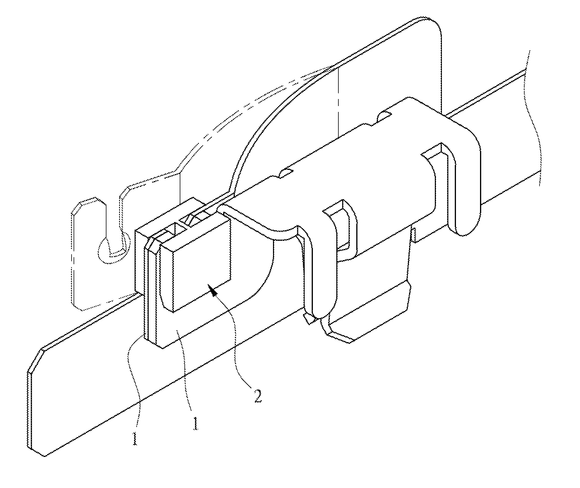
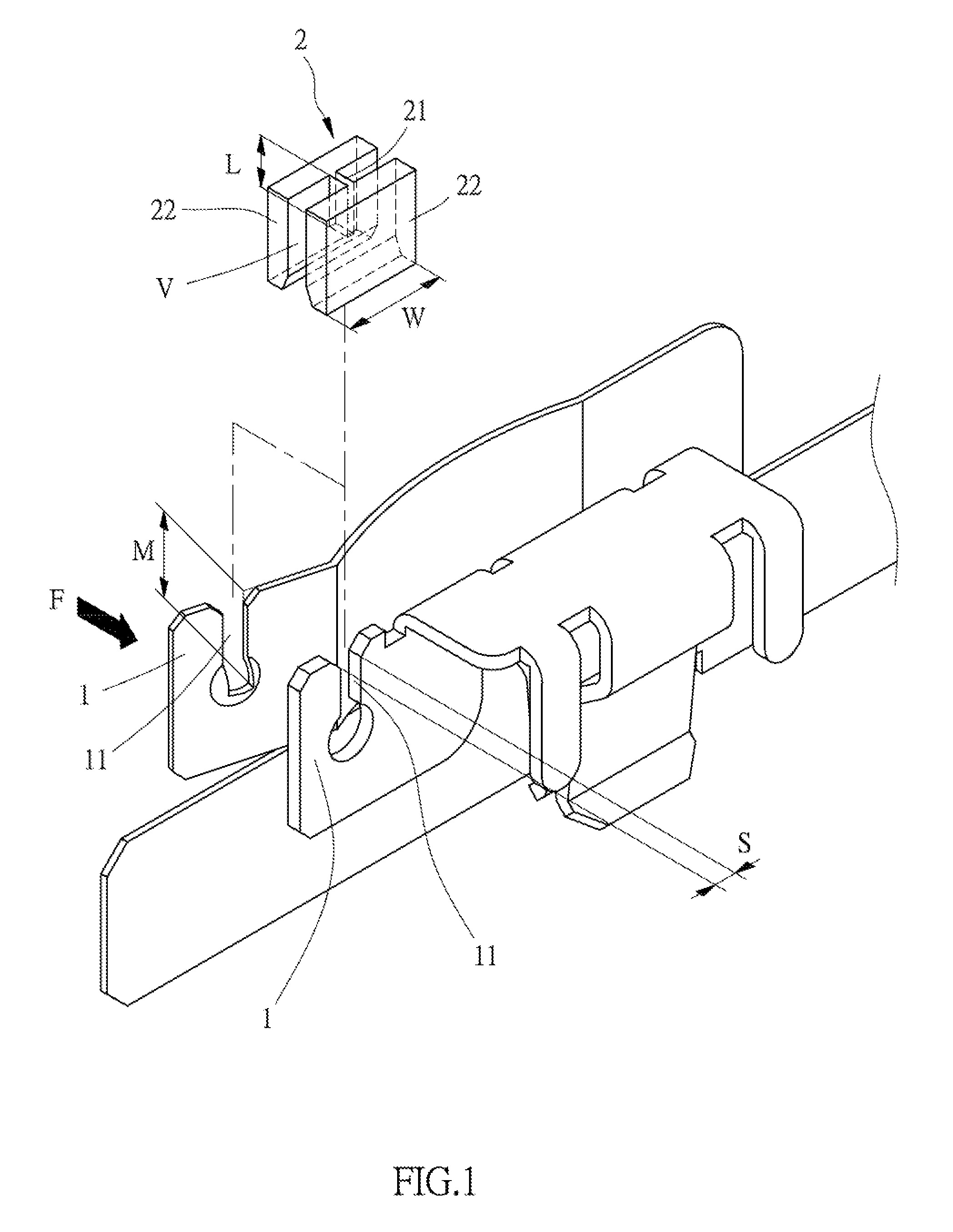
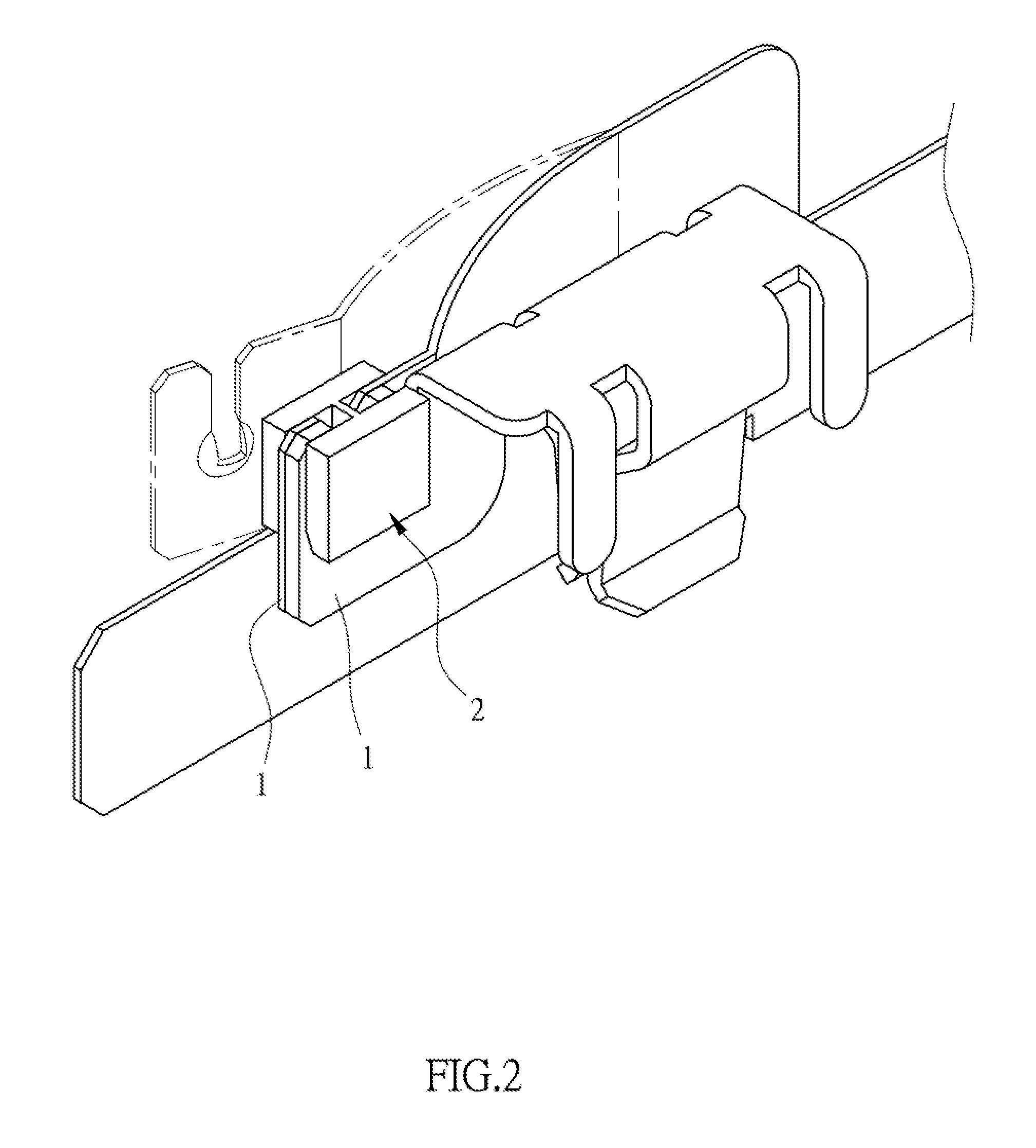
[0030]Referring to FIG. 1, an embodiment of the present invention comprises two conductive members 1. Each conductive member 1 is provided with a groove 11, and each groove 11 is concaved in from an edge of the host conductive member 1. The grooves 11 on the two conductive members 1 are opposite to each other, and a gap is maintained between the two conductive members 1 by an elastic force. The groove 11 is provided with a width S which is preferably between 0.1 cm and 1.3 cm. In the present embodiment, the groove width S is 0.8 cm.

[0031]Referring to FIGS. 1 to 4, the present embodiment further includes a hot melt fixing member 2. The hot melt fixing member 2 is provided with a connection member 21 and two stoppers 22 which are combined at two ends of the connection member 21. A holding space V is defined between the two stoppers 22. Two conductive members 1 are first close to and contact with each other by an external force F, and then the connection member 21 of the hot melt fixin...


PUM


Abstract

The present invention discloses a conductive terminal including two conductive members or further comprising a hot melt fixing member. Each conductive member is provided with a groove which is concaved in from an edge of the host conductive member. The grooves on the two conductive members are opposite to each other and a gap is maintained between the two conductive members by an elastic force between the conductive members. The hot melt fixing member is put into the grooves of the two conductive members and is combined on the conductive members to overcome the elastic force, enabling the two conductive member to form contact limit, the hot melt fixing member to be damaged when overheat, and the two conductive members to be opened by the elastic force to form open circuit. The conductive member can be applied to overheat protection of a plug and a socket.

Description

BACKGROUND OF THE INVENTION[0001](a) Field of the Invention[0002]The present invention relates to a conductive terminal, and more particularly to a conductive terminal which includes two conductive members, with each conductive member being provided with a groove which is concaved in from an edge of the host conductive member, and the two conductive members being combined with a hot melt fixing member, so that the two conductive members form contact limit to constitute an overheat protection structure for a path. In overheating, the hot melt fixing member is damaged that the two conductive members are opened by an elastic force to form open circuit.[0003](b) Description of the Prior Art[0004]To avoid current overload, short circuit or overheating to a circuit, a wire fuse or circuit breaker will be usually disposed on the circuit, such that the wire fuse will have melt fracture by high temperature when the temperature of the circuit is too high or metallic spring leaves of the circu...

Claims


Application Information

Patent Timeline
Patent Type & Authority Patents(United States)
IPC IPC(8): H01R13/44H01R13/696
CPCH01R13/696
Inventor WANG, CHUAN-SHENG
Owner GREEN IDEA TECH INC
Why Eureka
Try Eureka