Flat wiring body module

Inactive Publication Date: 2016-11-01
YAZAKI CORP
View PDF19 Cites 11 Cited by
  • Summary
  • Abstract
  • Description
  • Claims
  • Application Information

AI Technical Summary

Benefits of technology

[0007]The present disclosure has been made in view of the above described circumstances, and an object of the disclosure is to provide a flat wiring body module capable of achieving space saving, and at the same time, capable of being hardly affected by noises.
[0009]By the above configuration, because the flat wiring body formed by stacking the flat wiring body for power, the flat wiring body for non-power, and the flat wiring body for ground is adopted, it is possible to cope with the problem of space, by enhancing density of the circuits on the board, even though the number of the circuits increases, and hence, space saving can be achieved. Moreover, according to the disclosure, because the flat wiring body for ground is interposed between the flat wiring body for power and the flat wiring body for non-power, it is possible to avoid influences of noises on the circuit for non-power, by the presence of the flat wiring body for ground, even in case where the circuit for power becomes a noise source or a noise passage. Further, according to the disclosure, because the flat wiring body for ground is interposed as described above, it is possible to position the circuit for non-power remote from the circuit for power, by a thickness of the flat wiring body for ground.
[0010]Therefore, according to the disclosure, such an advantage that it is possible to save the space, and at the same time, to be hardly affected by influences of noises is achieved. Additionally, according to the disclosure, because the flat wiring body having the above described structure is adopted, such an advantage that it is possible to enhance freeness in designing is achieved.
[0012]According to the above configuration, because the flat wiring body for non-power is interposed between a plurality of the flat wiring bodies for ground, such an advantage that it is possible to avoid the influences of noises from the circuit for power, and besides, to avoid influences of noises from an exterior of the flat wiring body module too is achieved.

Problems solved by technology

In JP-A-2012-55105, there is such a problem that in case where a diameter of the wire harness grows larger following an increase of circuits in number, for example, it is necessary to secure a large space for arranging the wire harness according to the diameter.
Moreover, in the above described prior art, there is a further problem, as described below.

Method used


Image

  • Flat wiring body module
  • Flat wiring body module
  • Flat wiring body module

Examples


embodiments

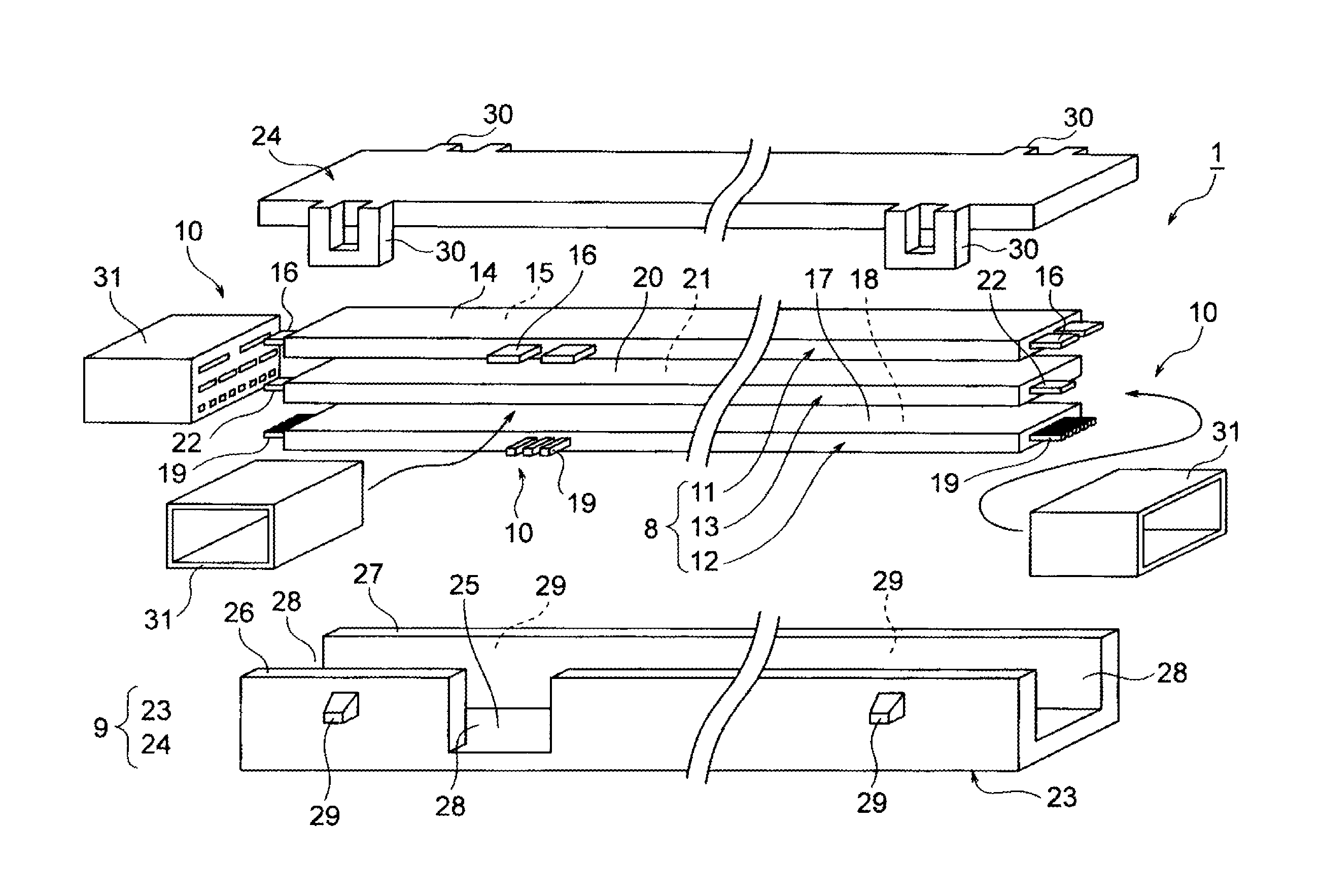
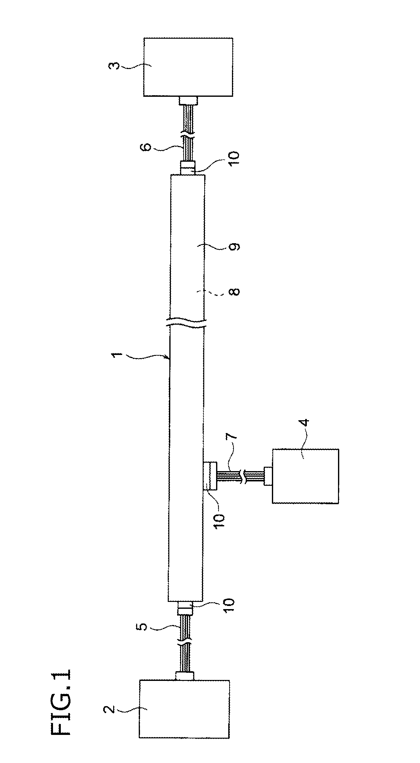
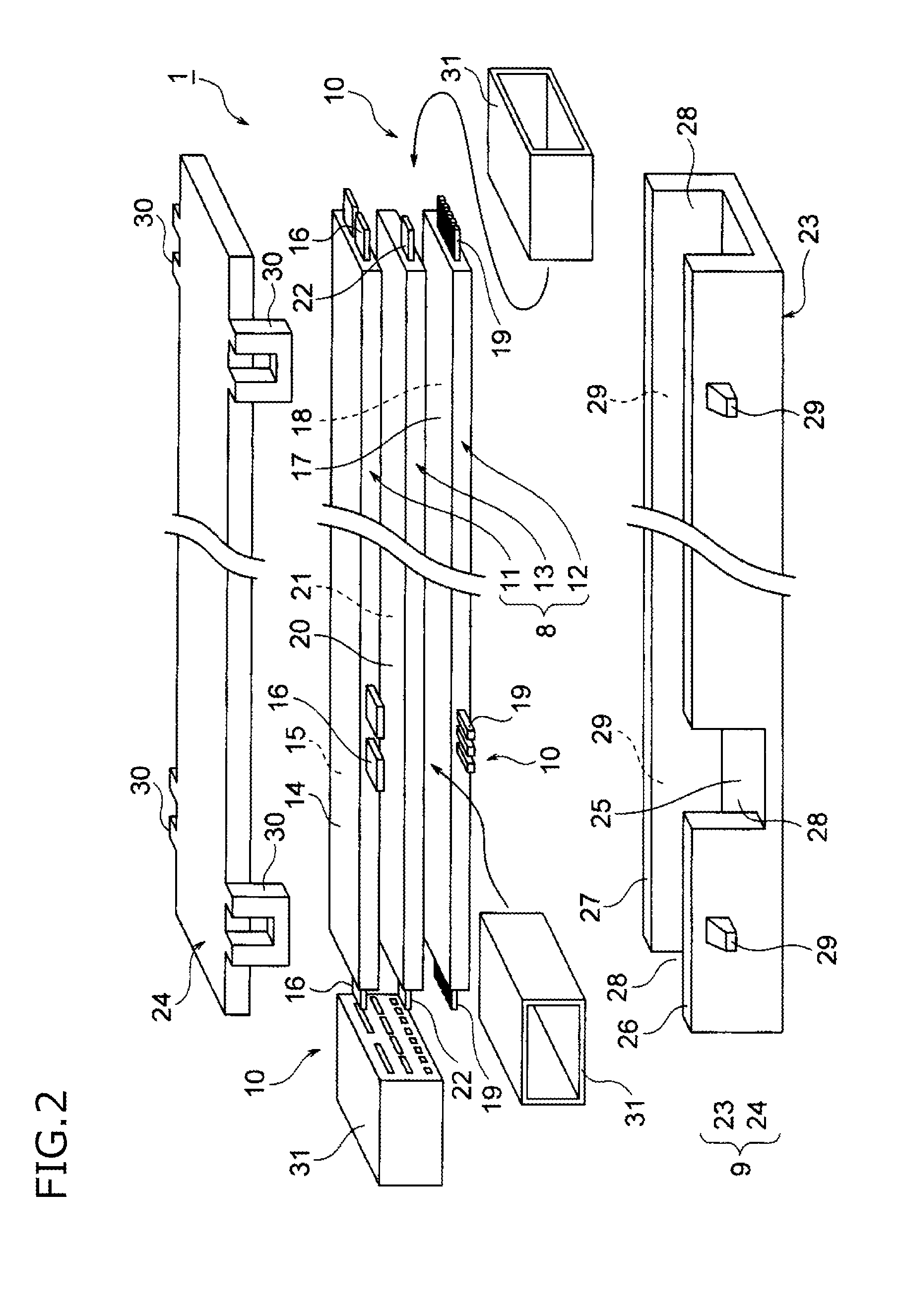
[0019]Several embodiments will be described below, referring to the drawings. FIG. 1 is a schematic view showing the flat wiring body module according to the disclosure, in an installed state. Moreover, FIG. 2 is an exploded perspective view of the flat wiring body module in FIG. 1, and FIG. 3 is an exploded perspective view and a perspective view of a flat wiring body in FIG. 2. Further, FIGS. 4 and 5 are exploded perspective views and perspective views of flat wiring bodies in other examples.

[0020]In FIG. 1, reference numeral 1 represents the flat wiring body module according to the disclosure. In this embodiment, this flat wiring body module 1 is used as a substitute for the wire harness in the prior art. Specifically, the flat wiring body module 1 is arranged along a reinforcing metal pipe in an instrument panel of a motor car (as one example, but may be also arranged, for example, in a side shell of the motor car). In this embodiment, the flat wiring body module 1 is disposed b...


PUM

PropertyMeasurementUnit
diameteraaaaaaaaaa
densityaaaaaaaaaa
thicknessaaaaaaaaaa

Abstract

A flat wiring body module includes a flat wiring body, a containing member containing the flat wiring body, and a connector part. The flat wiring body includes a flat wiring body for power including a power circuit and a first flat board, a flat wiring body for non-power including a non-power circuit and a second flat board, and a flat wiring body for ground including a ground and a third flat board. The flat wiring body for power, the flat wiring body for non-power, and the flat wiring body for ground are stacked in a state where the flat wiring body for ground is arranged between the flat wiring body for power and the flat wiring body for non-power.

Description

CROSS REFERENCE TO RELATED APPLICATION[0001]This application is based on Japanese Patent Application (No. 2014-238365) filed on Nov. 26, 2014, the contents of which are incorporated herein by reference. Also, all the references cited herein are incorporated as a whole.BACKGROUND[0002]1. Technical Field[0003]The present invention relates to a flat wiring body module provided with a flat wiring body which is formed by stacking a plurality of wiring bodies.[0004]2. Background Art[0005]Conventionally, a wire harness has been arranged in an instrument panel of a motor car. Generally, this wire harness is arranged along a reinforcing metal pipe. The wire harness is formed by bundling a plurality of electric wires into a substantially round shape in cross section. In arranging the wire harness as described above, a relatively large protector capable of containing the wire harness has been used (Refer to JP-A-2012-55105).[0006]In JP-A-2012-55105, there is such a problem that in case where a...

Claims


Application Information

Patent Timeline
Patent Type & Authority Patents(United States)
IPC IPC(8): H01R12/78H05K9/00H01B7/08H02G5/06B60R16/02
CPCH05K9/00H01B7/08H02G5/06B60R16/0207H01R11/11H02G3/045H01B7/0045H01B13/01254
Inventor NAKATA, ATSUSHI
Owner YAZAKI CORP
Why Eureka
Try Eureka