
Vehicular curtain air-bag device, and mounting structure for same

a technology for vehicular curtain and airbags, which is applied in the direction of vehicular safety arrangments, pedestrian/occupant safety arrangements, vehicular components, etc., can solve the problems of unpractical 1110763a1 and prevent the provision of desired occupant protection performance, and achieves simple configuration, increased productivity, and easy and efficient attachment operations.

Active Publication Date: 2016-11-08
AUTOLIV DEV AB
View PDF21 Cites 20 Cited by
  • Summary
  • Abstract
  • Description
  • Claims
  • Application Information

AI Technical Summary

Benefits of technology

[0033]The vehicular curtain airbag apparatus and the attachment structure therefor according to the present invention do not interfere with a driver seat airbag or a passenger seat airbag and can appropriately provide the occupant protection performance either in a normal collision mode in which the driver and passenger seat airbags function or in a small-overlap mode. Furthermore, the curtain airbag and the attachment structure used to attach the airbag to the vehicle have simple configurations, enable productivity to be increased, and allow attachment operations to be more easily and efficiently performed. In the small overlap mode, at what angle the occupant rushes in is unknown. However, the first tab functions effectively in such a contingency situation to allow the occupant protection performance to be more reliably provided.

Problems solved by technology

Thus, disadvantageously, WO 2012 / 1110763A1 is unpractical.
Thus, disadvantageously, the interference may prevent exertion of a regular deploying and inflating function of the driver seat airbag or the like or sufficient deployment and inflation of the additional chamber or the like, precluding desired occupant protection performance from being provided.

Method used


Image

  • Vehicular curtain air-bag device, and mounting structure for same
  • Vehicular curtain air-bag device, and mounting structure for same
  • Vehicular curtain air-bag device, and mounting structure for same

Examples


Embodiment Construction

[0050]A preferred embodiment of a vehicular curtain airbag apparatus and an attachment structure therefor according to the present invention will be described below with reference to the attached drawings.

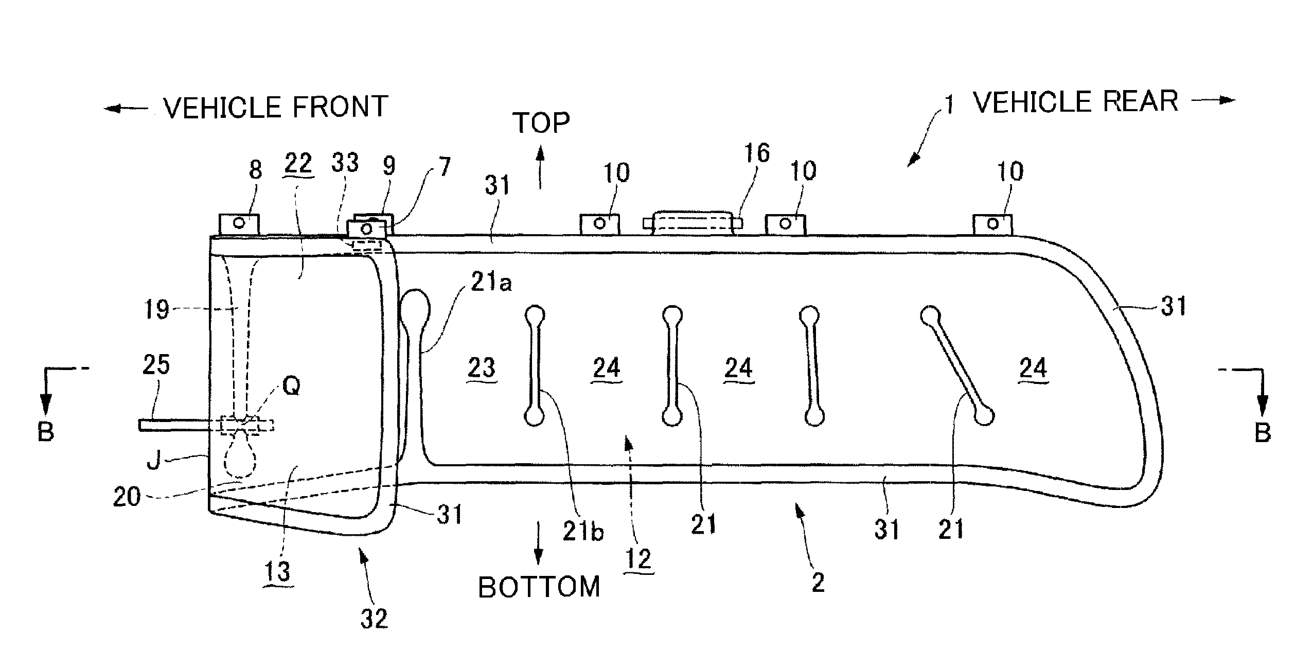
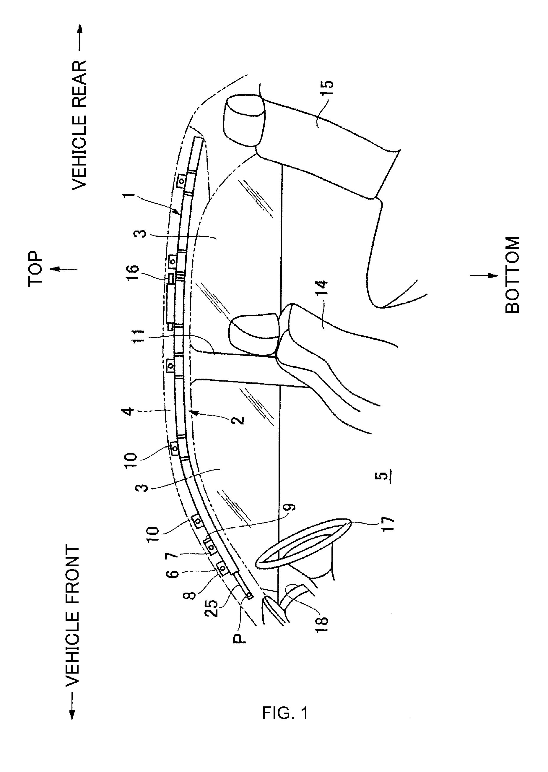
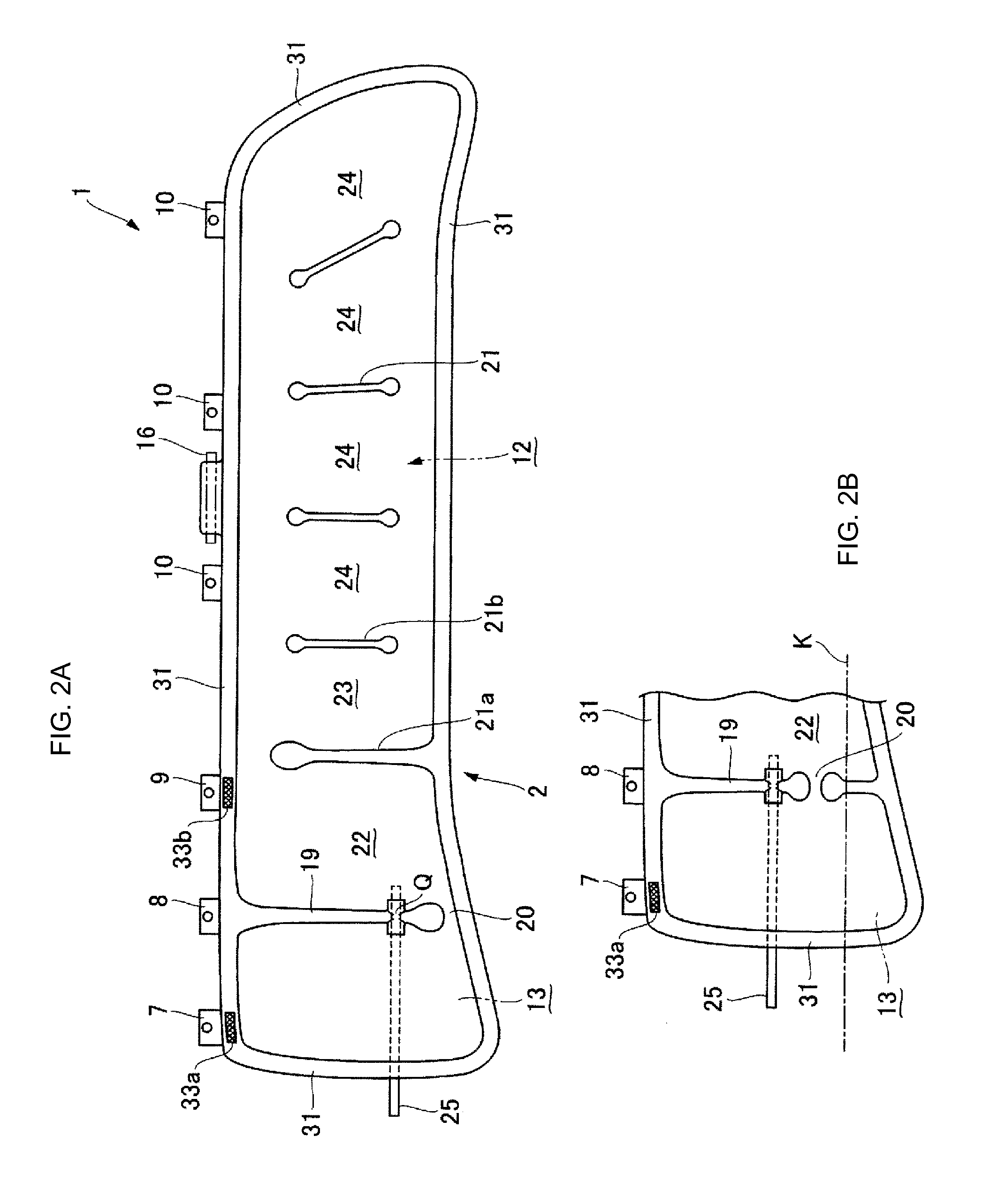
[0051]FIG. 1 is a side view of a housed state of the vehicular curtain airbag apparatus according to the present embodiment that is attached and fixed to a vehicle. FIGS. 2A and 2B and FIGS. 3A and 3B are diagrams illustrating a non-inflation state of the vehicular curtain airbag apparatus according to the present embodiment. FIG. 2A is a front view of an additional chamber that is not folded back yet. FIG. 2B is a front view depicting an important part of a variation. FIG. 3A is a front view of the additional chamber that has been folded back toward a vehicle interior of a main chamber. FIG. 3B is a front view depicting an important part of a variation. FIG. 4 is a sectional view of the vehicular curtain airbag apparatus taken along line B-B depicted by arrows in FIG. 3A. FIG. 5 i...


PUM


Abstract

A vehicular curtain airbag apparatus and an attachment structure configured not to interfere with a driver seat airbag and being able to appropriately provide occupant protection performance either in normal and small overlap collision modes, and the curtain airbag having a simple configuration. The apparatus includes a main chamber having a front end to be deployed and inflated at a position near a front pillar, and an additional chamber further toward a vehicle front side and to be deployed and inflated, and separated from the main chamber by a partition portion between the front pillar and an inflation area of a driver seat airbag. The additional chamber is folded back near the partition portion toward the vehicle interior and a rear of the vehicle to overlap the main chamber, and parts of a resultant overlapping portion corresponding to upper portions of the main and additional chambers or vicinities of the parts are coupled together to form a chamber coupling portion.

Description

CROSS REFERENCE TO RELATED APPLICATIONS[0001]This application claims priority to Japanese Patent Application Nos. 2013-109307, filed May 23, 2013, 2013-118295, filed Jun. 4, 2013 and PCT / JP2014 / 062803, filed on May 14, 2014.FIELD OF THE INVENTION[0002]The present invention relates to a vehicular curtain airbag apparatus that does not interfere with a driver seat airbag or a passenger seat airbag and that can appropriately provide occupant protection performance either in a normal collision mode, in which the driver and passenger seat airbags and a curtain airbag function, or in a small-overlap mode, with the curtain airbag being configured to have a simple airbag configuration and a simple structure for attachment to the vehicle. The present invention also relates to an attachment structure for the vehicular curtain airbag apparatus.DESCRIPTION OF THE RELATED ART[0003]Forms of vehicular collisions include a small overlap mode, and effort has been made to improve occupant protection ...

Claims


Application Information

Patent Timeline
Patent Type & Authority Patents(United States)
IPC IPC(8): B60R21/232B60R21/2338B60R21/233B60R21/213B60R21/231
CPCB60R21/232B60R21/213B60R21/233B60R21/2338B60R21/23138B60R2021/23161B60R2021/23324B60R2021/23386
Inventor NAKASHIMA, ATSUSHI
Owner AUTOLIV DEV AB
Learn More