Transmission line transformer antenna

a transformer antenna and transmission line technology, applied in the direction of waveguides, waveguide type devices, electrical equipment, etc., can solve the problems of antennas transmitting unbalanced transmission signals and input ports receiving unbalanced input radio frequency signals

Active Publication Date: 2016-11-08
LILLY JAMES D +1
View PDF2 Cites 6 Cited by
  • Summary
  • Abstract
  • Description
  • Claims
  • Application Information

AI Technical Summary

Problems solved by technology

The input port can receive an unbalanced input radio frequency signal.
The antenna can transmit an unbalanced transmission signal based on the input radio frequency signal.

Method used


Image

  • Transmission line transformer antenna
  • Transmission line transformer antenna
  • Transmission line transformer antenna

Examples


Embodiment Construction

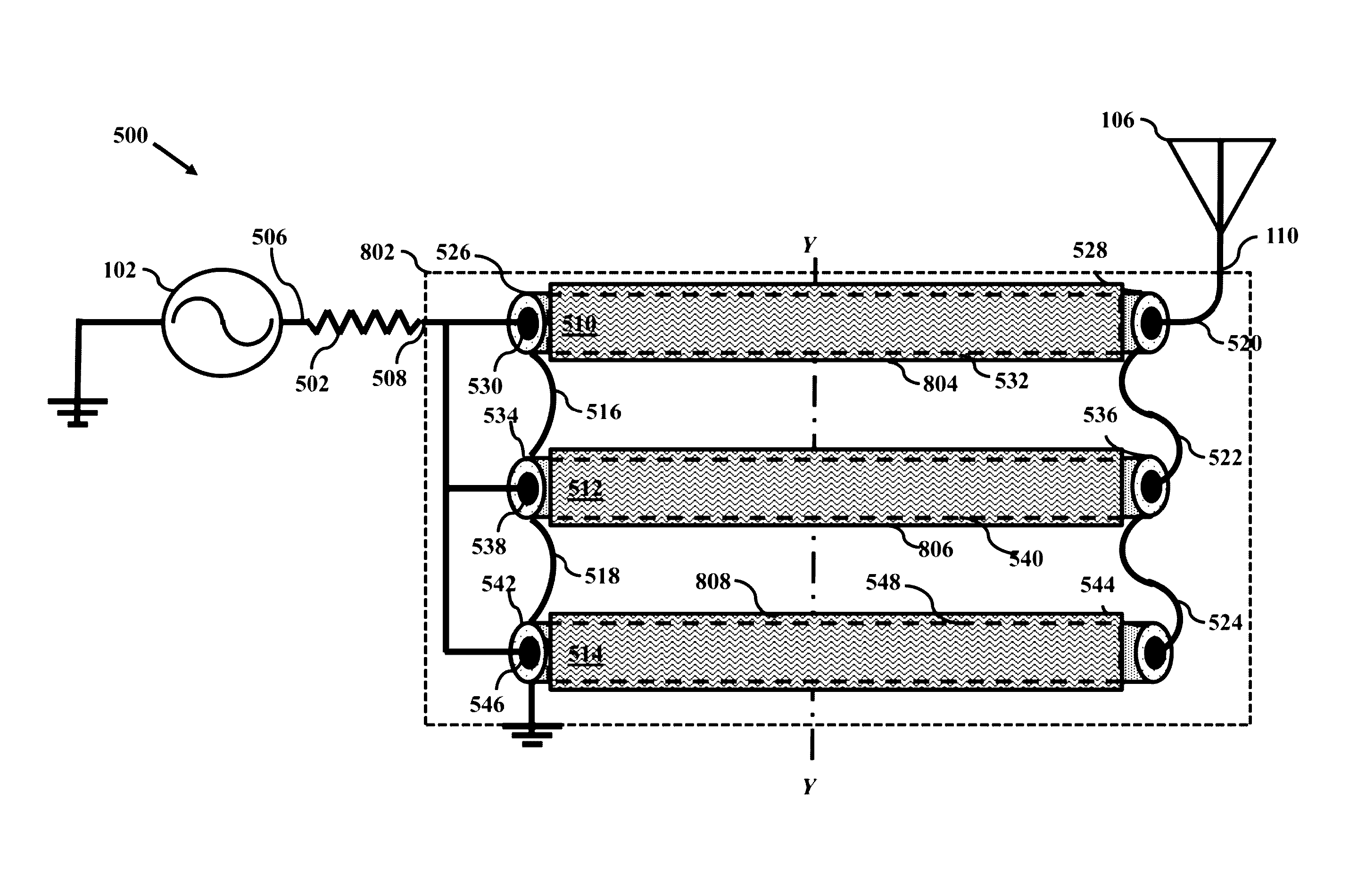
[0042]The present invention is drawn a short whip antenna using a transmission line transformer for impedance matching, between the signal generator and the short whip antenna. Further, the transmission line transformer uses specifically displaced beads of impedance increasing material on the coaxial transmission line transformers. The beads of impedance increasing material greatly reduce induced back currents (common-mode currents) on the outer surfaces of the coaxial transmission line transformers, which decreases interference with the transmitted signal from the short Whip antenna. The specific displacement of the beads enables the coaxial transmission line transformers to be compactly disposed within a heat sink.

[0043]Transmission line transformers are well known. However, they are typically used between a balanced input and unbalanced output—as a “balun.” In accordance with aspects of the present invention, a transmission line transformer is used between an unbalance input and ...


PUM


Abstract

The present invention is drawn a transmission line transformer that uses specifically displaced beads of impedance increasing material on the coaxial transmission lines. The beads of impedance increasing material greatly reduce induced back currents on the outer surfaces of the coaxial transmission lines, which reduces losses and improves performance. The specific displacement of the beads enables the coaxial transmission lines to be compactly disposed within a heat sink.

Description

BACKGROUND[0001]The present invention generally relates to hand held communication devices employing whip antennas. A whip antenna is an antenna having a single straight flexible wire or rod. The bottom end of the whip is connected to the radio receiver or transmitter.[0002]For hand-held long range communications, the band is typically in the range of 2-30 MHz. The shorter frequencies have the ability to follow the contours of Earth. This is one of the few benefits over high frequency communications, which may be more limited to line of sight. Unfortunately, as frequency reduces, the whip length should increase to maintain efficiency.[0003]Some conventional hand-held whip antenna communication devices that operate in the 90-500 MHz band have a whip antenna of lengths of about four feet. Such a length is not very practical for a hand-held device. A tri-fold version provides a collapsible antenna having a much shorter length when not in use. However the folded antenna must be deployed...

Claims


Application Information

Patent Timeline
Patent Type & Authority Patents(United States)
IPC IPC(8): H03H7/38H01P5/10H01P5/12H01P5/02H01Q1/50H01P3/06
CPCH01P5/02H01P3/06H01Q1/50H01P5/12
Inventor LILLY, JAMES DWILSON, MINOR C
Owner LILLY JAMES D
Why Eureka
Try Eureka