Programmable synchronous clock divider

a clock divider and synchronous technology, applied in the field of integrated circuits, can solve problems such as duty cycle degradation and affecting data paths inside the ics

Active Publication Date: 2016-11-08
NXP USA INC
View PDF16 Cites 1 Cited by
  • Summary
  • Abstract
  • Description
  • Claims
  • Application Information

AI Technical Summary

Problems solved by technology

Aging of sequential elements (silicon aging) and chip variations (e.g., due to process, voltage and temperature) may result in duty cycle degradation, thereby affecting data paths inside the ICs.
Aging-induced duty cycle shift may occur in a particular direction (increased fall-delays or increased rise delays) depending on types of asymmetric components in a clock tree topology.

Method used


Image

  • Programmable synchronous clock divider
  • Programmable synchronous clock divider
  • Programmable synchronous clock divider

Examples


Embodiment Construction

[0017]The detailed description of the appended drawings is intended as a description of the currently preferred embodiments of the present invention, and is not intended to represent the only form in which the present invention may be practiced. It is to be understood that the same or equivalent functions may be accomplished by different embodiments that are intended to be encompassed within the scope of the present invention. The terms multiplexer and mux are used interchangeably.

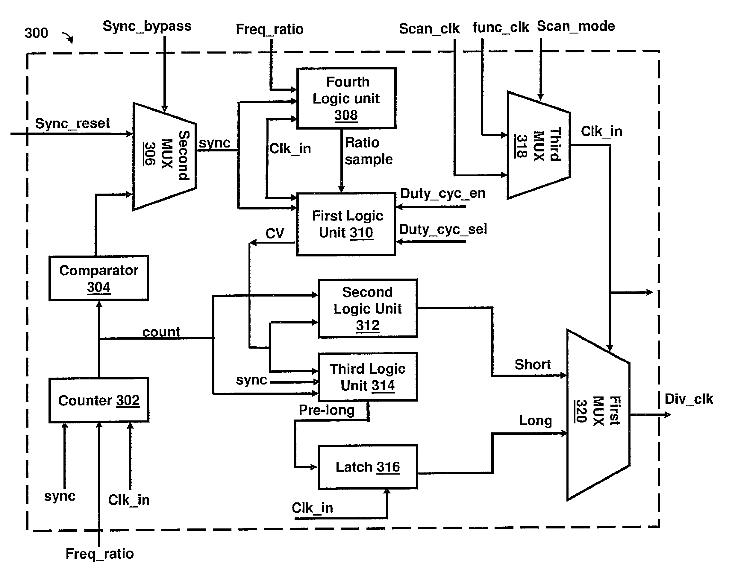
[0018]The present invention is directed to a synchronous clock divider for generating divided clock signals with programmable duty cycle and programmable divide ratio. The clock divider may include one or more sequential logic elements. These sequential logic elements may comprise a counter for generating a count value at a rising edge of the input clock signal, and a comparator for comparing the count value with a ratio sample value (ratio_sample) (a constant number that may be predefined) for input clock...


PUM


Abstract

A divided clock signal is generated from an input clock signal. The duty cycle of the divided clock signal is programmed by generating a compare value based on values of duty cycle input and a divide value of the input clock signal. The compare value is compared to a count value to generate short and long pulse signals. The divided clock signal is generated based on the short and long pulse signals. The duty cycle of the divided clock signal varies in accordance with the compare value.

Description

BACKGROUND OF THE INVENTION[0001]The present invention relates generally to integrated circuits, and, more particularly, to a synchronous clock divider integrated circuit.[0002]Integrated circuits (ICs) include many sequential elements such as flip-flops, and latches. The frequency of operation of the sequential elements is governed by the cycling rate of clock signals. Duty cycle is an ON period of a single cycle of a clock signal. The duty cycle represents the ON time of a clock signal supplied to sequential elements. The cycling rate of the clock signals may be changed by changing divide ratios of clock divider circuit. The divide ratio is used to change the clock frequency of the clock signals.[0003]Aging of sequential elements (silicon aging) and chip variations (e.g., due to process, voltage and temperature) may result in duty cycle degradation, thereby affecting data paths inside the ICs. Aging-induced duty cycle shift may occur in a particular direction (increased fall-delay...

Claims


Application Information

Patent Timeline
Patent Type & Authority Patents(United States)
IPC IPC(8): H03K21/00H03K3/017H03K23/00H03K21/10H03K21/02
CPCH03K3/017H03K23/002H03K21/00H03K21/026H03K21/10H03K23/00H03K5/1565
Inventor ALI, INAYATDODEJA, PUNEETJAIN, SACHIN
Owner NXP USA INC
Why Eureka
Try Eureka