Apparatus and method for indirect surface cleaning

a surface cleaning and apparatus technology, applied in the field of apparatus, can solve the problems of significant increase in problems, limited application of systems, and limited ability to end the removal process at the substrate interfa

Active Publication Date: 2009-02-12
BRUKER NANO INC
View PDF29 Cites 29 Cited by
  • Summary
  • Abstract
  • Description
  • Claims
  • Application Information

AI Technical Summary

Benefits of technology

[0016]At least in view of the above discussion, it would be advantageous to develop an alternative cleaning method and/or appa...

Problems solved by technology

These systems can be limited in application because of peak powers achievable.
However, substrates that have high absorption at the selected wavelengths are likely to be ablated along with the contamination, even with wavelength selection and multiple pulse removal processes.
The ability to end stop the removal process at the substrate interface will be limited in these cases.
This problem is significantly increased for smaller size contamination, since the absorption cross section for the contamination is reduced relative to the substrate.
As with ablative removal processes, particulate removal processes can also cause substrate damage for sensitive substrates and substrates that have high absorption at the processing wavelength.
This problem is increased for small particle removal because of increased adhesion forces between the particles and substrate and self focusing of the laser underneath the particles.
However, with the exception of dry laser cleaning processes, all of the particulate removal processes described require access to the environment above the substrate surface.
This may be impractical for some systems.
Laser acoustic wave cleaning involves direct excitation to the substrate and therefore suffers from a high potential for substrate damage particularly for small particles as discussed.
This technique will also have increased difficulty when applied to small particle removal.
In addition, the shock wave may damage other sensitive features on or near the surface of the substrate.
Even the newest dry laser techniques can also be limited in cases where access to the environment above the surface is not practical (e.g., enclosed systems).
Cleaning is an issue in multiple wafer processing steps and includes extended contamination layer (e.g., resist removal) and particulate contamination remova...

Method used


Image

  • Apparatus and method for indirect surface cleaning
  • Apparatus and method for indirect surface cleaning
  • Apparatus and method for indirect surface cleaning

Examples


Embodiment Construction

[0059]The invention will now be described with reference to the drawing figures, in which like reference numerals refer to like parts throughout. According to certain embodiments of the present invention, a method for laser surface cleaning with a reduced risk of substrate damage is provided.

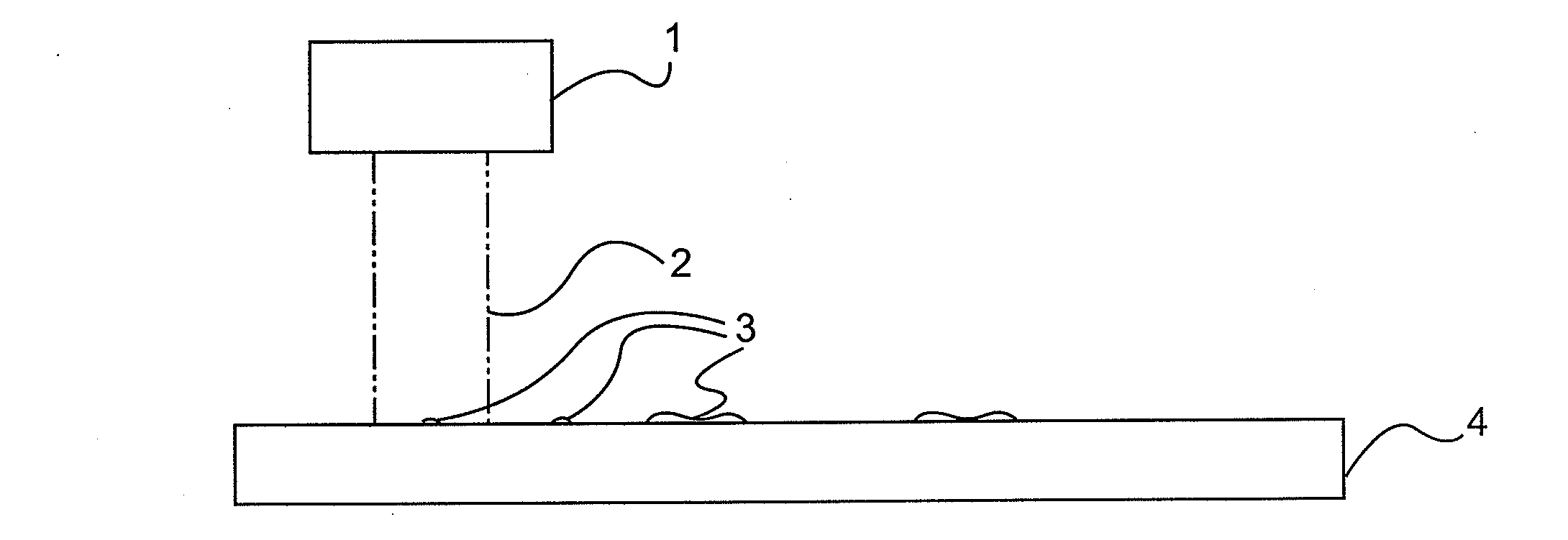
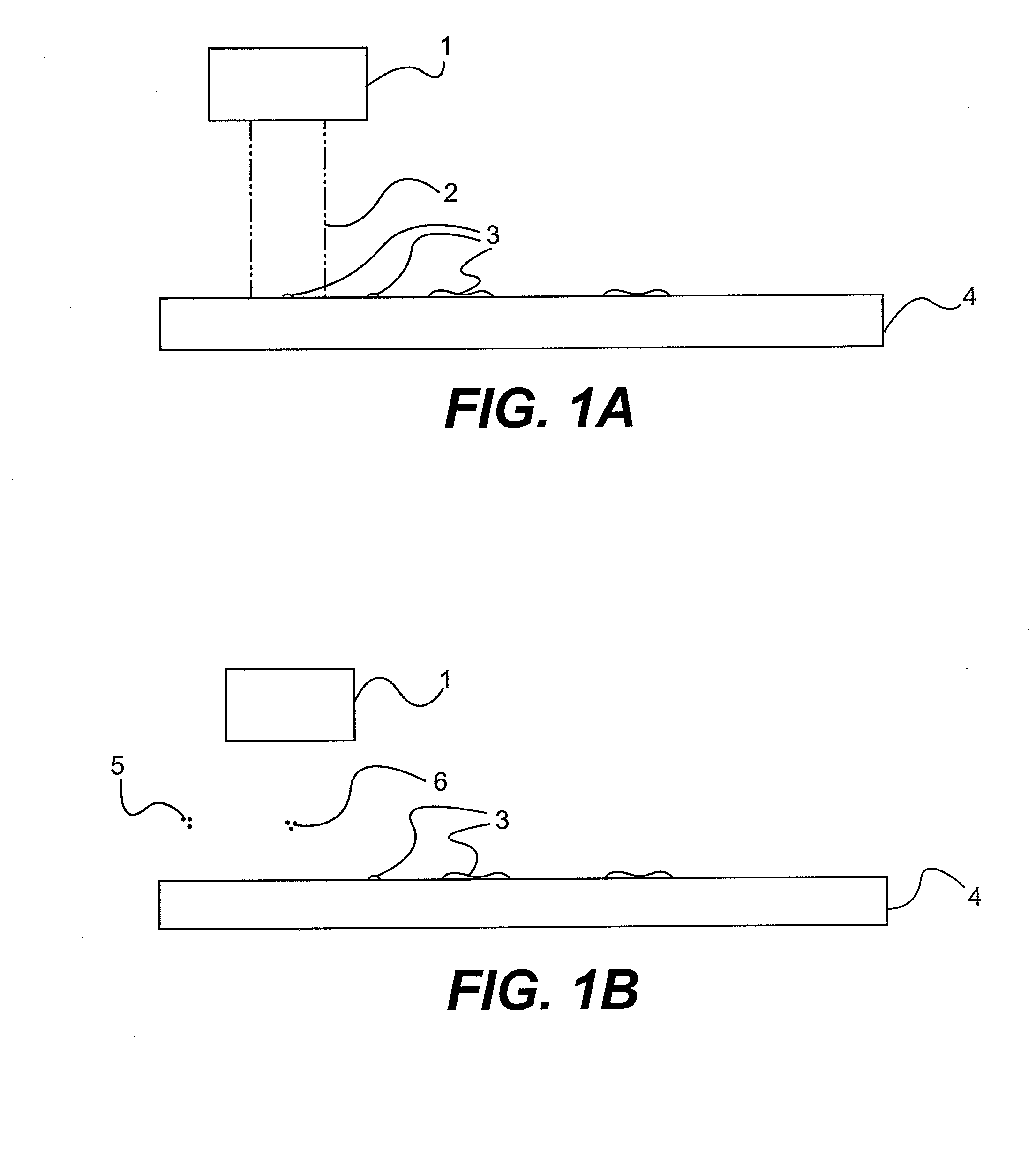
[0060]FIG. 1A illustrates an embodiment of the present invention in which an excitation energy 2 comes from an energy source, such as a laser 1 and is directed towards the contaminated substrate's 4 surface resulting in thermal transfer from the substrate's 4 surface to the contaminating particulate 3 or contamination layer (e.g., by convection or conduction). However, energy sources other than laser may also be used (e.g., lamps and other devices that can radiate energy all along the electromagnetic spectrum may be used, including generators or x-rays, microwaves, infrared radiation, near-ultraviolet radiation, etc.). Also, the surface may be of any material (e.g., the surface of a silicon wafe...


PUM

PropertyMeasurementUnit
Temperatureaaaaaaaaaa
Widthaaaaaaaaaa
Wavelengthaaaaaaaaaa

Abstract

A method for laser surface cleaning of a target surface that has limited or no access to the environment directly above the surface to be cleaned. The method includes the ability to clean the surface with a reduced risk of substrate damage. The method includes direct laser excitation of a contaminated substrate surface and thermal transfer from the substrate to the contaminating particulate or contamination layer. The method also includes producing a thermally based removal and reducing a risk of substrate damage by keeping the temperature required to produce surface cleaning below the thermal damage level of the substrate material. In addition, the method includes reducing the risk of substrate damage by utilizing relatively long pulse-widths, providing for improved removal of small contaminants/particles, and directing the beam through a material disposed relative to the surface that is part of the substrates environmental enclosure.

Description

CROSS-REFERENCE TO RELATED APPLICATIONS[0001]This application claims priority to provisional U.S. patent application entitled, APPARATUS AND METHOD FOR INDIRECT SURFACE CLEANING, filed Aug. 9, 2007, having a Ser. No. 60 / 954,989, disclosure of which is hereby incorporated by reference in its entirety.FIELD OF THE INVENTION[0002]The present invention relates generally to devices and methods useful in cleaning surfaces. More particularly, the present invention relates to devices and methods useful in cleaning surfaces of components typically used in the semiconductor industry, optics, etc. The devices and methods disclosed are applicable to extending the useful life of photomask reticles.BACKGROUND OF THE INVENTION[0003]Electromagnetic radiation has long been used for surface cleaning. Examples of these processes include the removal of surface contamination, removal of thin material layer coatings such as paints or removal of oils from metal work surfaces. Some of the earliest examples...

Claims


Application Information

Patent Timeline
IPC IPC(8): B08B7/00
CPCB08B7/0042Y10S134/902G03F1/82
Inventor LECLAIRE, JEFFREY E.ROESSLER, KENNETH GILBERTBRINKLEY, DAVID
Owner BRUKER NANO INC
Why Eureka
Try Eureka