System and method for more efficient automatic irrigation based on a large number of cheap humidity sensors and automatic faucets

a technology of automatic irrigation and humidity sensor, which is applied in the field of automatic irrigation with humidity sensors, can solve the problems of less efficiency and 2 options, and achieve the effects of saving work and time, reducing labor intensity, and improving efficiency

Active Publication Date: 2016-11-15
MAYER BATYA BARHON +1
View PDF13 Cites 4 Cited by
  • Summary
  • Abstract
  • Description
  • Claims
  • Application Information

AI Technical Summary

Benefits of technology

[0010]The solution for flowerpots is similar, except that the sensing can be done even more efficiently and even more cheaply, and also the control of the watering itself can be done more efficiently and more cheaply, by taking advantage of certain features of flowerpots, as explained below. Therefore, the solution or flowerpots can be regarded also as a smart-home gadget, since it uses smart and cheap automation to both save work and time and to save water.
[0011]In gardens and agricultural fields preferably one or more main pipes are used with sufficient water pressure of for example 1 or more atmospheres, and each pipe preferably extends into smaller channels that go for example sideways, each preferably with a much lower pressure. This way, the valve that is needed to control each of these small channels needs much less force and therefore can be much cheaper than an ordinary electronic faucet. The reduced pressure can be created for example by using long twisted small conduits at or before each side-channel that easily lower the water flow (such as for example in the pipes by Queen-Gil), which is very cheap and efficient. Another possible variation is using for example a set of preferably small water collectors that work like a toilet's Niagara (preferably one for each side channel), or using mechanical pressure reducers (however these last 2 options are less efficient). This general configuration is shown in FIGS. 1 & 1a-b. The sensing can be for example mechanical, so that for example a sponge or wood or hair (or other material that changes it shape when it becomes wetter or drier) closes or opens a valve or for example applies pressure to a flexible pipe for example directly by its own mechanical change of shape or indirectly through activating an electrical element (Preferable solutions for this are shown for example in FIGS. 2a-i). One of the most interesting of these variations is mechanical sensors based on a bi-material of two or more materials which expand differently when they become wet, thus converting the difference of the expansion into convenient movement. Or the sensing and control can be done electrically, but preferably in very cheap and efficient ways, as described below (Preferable solutions for this are shown for example FIGS. 3a-d &4a-c), or the sensing and control can be based on physical and / or chemical tendencies of the water itself, preferably by using asymmetric and / or irregular and / or strong capillary material or materials, as explained above and in FIG. 6.
[0013]Another possible variation is to use similar principles like those of the solutions for the flowerpots—also for gardens and / or fields, for example by inserting (preferably more or less horizontally) a water-blocking material (such as for example a preferably strong plastic or nylon) below the plants, for example by removing 1-2 meters of earth, adding the material, and adding back the earth on top, preferably before planting the plants. The blocking material is preferably also hard enough so as not to be distorted in shape too much by the pressure from above and by the contours of land and rocks below, and preferably has also for example vertical walls around itself, so as to create one or more large pool isolating the earth with the plants above that pool from the rest of the earth below and around. This way, although the humidity sensors have to work more like in the solutions described above for gardens and fields than the special solutions that can work with water dishes with flowerpots, still the usage of water can be much more efficient since the earth in the area of the plants can be kept at higher humidity levels with less water than in a normal garden or field where excess water can always escape further below into the ground. This can work even if the blocking material does not seal the area hermetically but only significantly reduces the rate in which water can escape away downwards. Like with the flowerpot dishes, the water blocking material can also be for example based on an array of elongated structures that look like bottom-halves of large pipes, that are inserted into the ground and covered with a layer of earth upon which for example vegetables or other agricultural products can be grown more efficiently.
[0014]Another possible variation, which can be applied in combination with any of the other variations, is to supply the plants with the same water supply system, also with other nutrients in addition to the water, such as for example liquid fertilizers and / or minerals, and / or for example air or CO2 or oxygen (for example by using Soda water with various degrees of CO2 melted in the water) in order to further help stimulate the plant's growth. Such additional materials can be added for example all the time in the desired quantities as a certain percent of the water, and / or part of the time with the aid of an automatic time schedule, and / or together with additional sensing (for example when the naturally occurring electrical potential in the earth indicates too low salinity, or when there is indication of too little air in the ground, and / or for example depending on the level of humidity, etc.). The addition of air or CO2 or other gases is especially important, since, apart from speeding up plant growth, it can also protect its roots from rotting, since the main cause for rotting in roots is the lack of air when they are immersed too much in water. This addition of gases such as for example air or Oxygen or CO2 can be used also in combination with hydrophonic or hydrostatic irrigation methods, since the main problem that limits the use of such methods to only a limited variety of plants is that in many plants the roots rot under such conditions due to lack of air. However, adding for example air or Oxygen instead of CO2 is more preferable, since the absorption of CO2 in water makes them acidic. Since (unlike leafs) the roots need Oxygen, adding Oxygen to the water supply can help the plant thrive even at levels of 100% humidity.
[0015]Another possible variation, which can be applied in combination with any of the other variations, is adding a feedback system for automatically reporting problems for example to a central control unit, such as for example flooding or blockages. One way of accomplishing this is by allowing for example each valve or sensor at the side channels to report back the approximate amount of water passed by it and / or the percent of time it remained open and / or for example to report significant changes in conditions, such as for example suddenly finding much more humidity in a certain area, or finding that the area remains dry despite the attempts of the sensor to open the valve. (However, increase in humidity can also be caused by rain for example so this is preferably reported to the user by the central control only if it deviates significantly from other sub-areas). However this can make the system a little more expensive. Another possible variation is to use a hierarchy of more than 2 levels, so that there are not only main pipes and side channels but also one or more intermediary levels, and preferably intermediary junctures are responsible for indication and / or reporting of such problems, which is cheaper to implement, since in this case only these junctures have to be smarter. For these junctures the more preferred variation is that they simply have a cheap water-meter and report back to the center and / or to the main supply of each main pipe the approximate amount of water consumed per time period, and / or each main pipe for example has its own water-meter and reports this, and then either the human operator or a preferably cheap processor at the center can easily notice if there are significant deviations.

Problems solved by technology

Another possible variation is using for example a set of preferably small water collectors that work like a toilet's Niagara (preferably one for each side channel), or using mechanical pressure reducers (however these last 2 options are less efficient).
Also, the same methods or principles described for gardens and fields can be also used with flowerpots, however that could be less efficient, except in the case of asymmetric capillary materials, which might be the best method also for flowerpots.

Method used


Image

  • System and method for more efficient automatic irrigation based on a large number of cheap humidity sensors and automatic faucets
  • System and method for more efficient automatic irrigation based on a large number of cheap humidity sensors and automatic faucets
  • System and method for more efficient automatic irrigation based on a large number of cheap humidity sensors and automatic faucets

Examples


Embodiment Construction

[0025]All of descriptions in this and other sections are intended to be illustrative examples and not limiting.

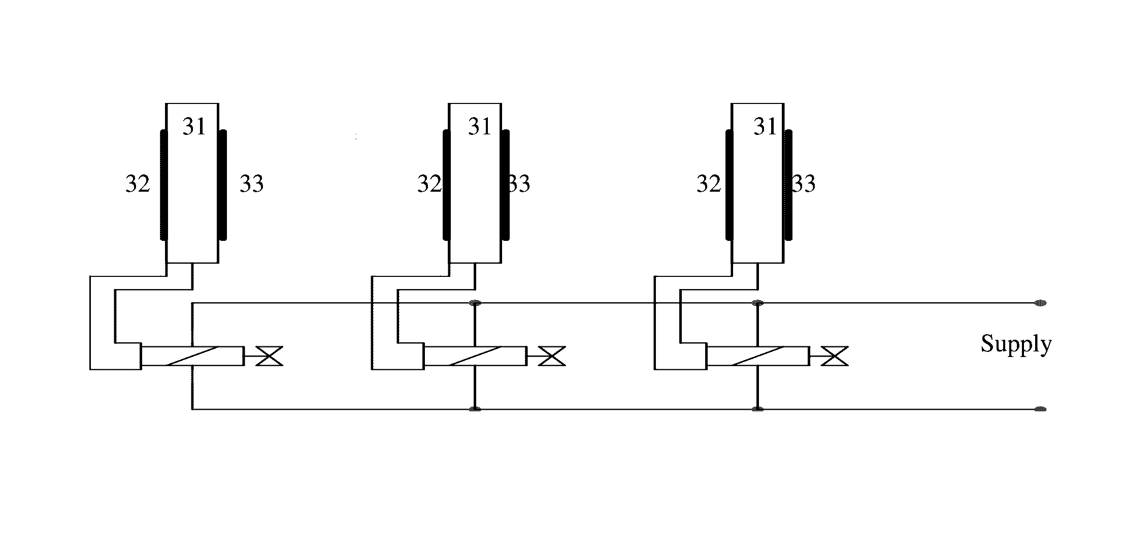
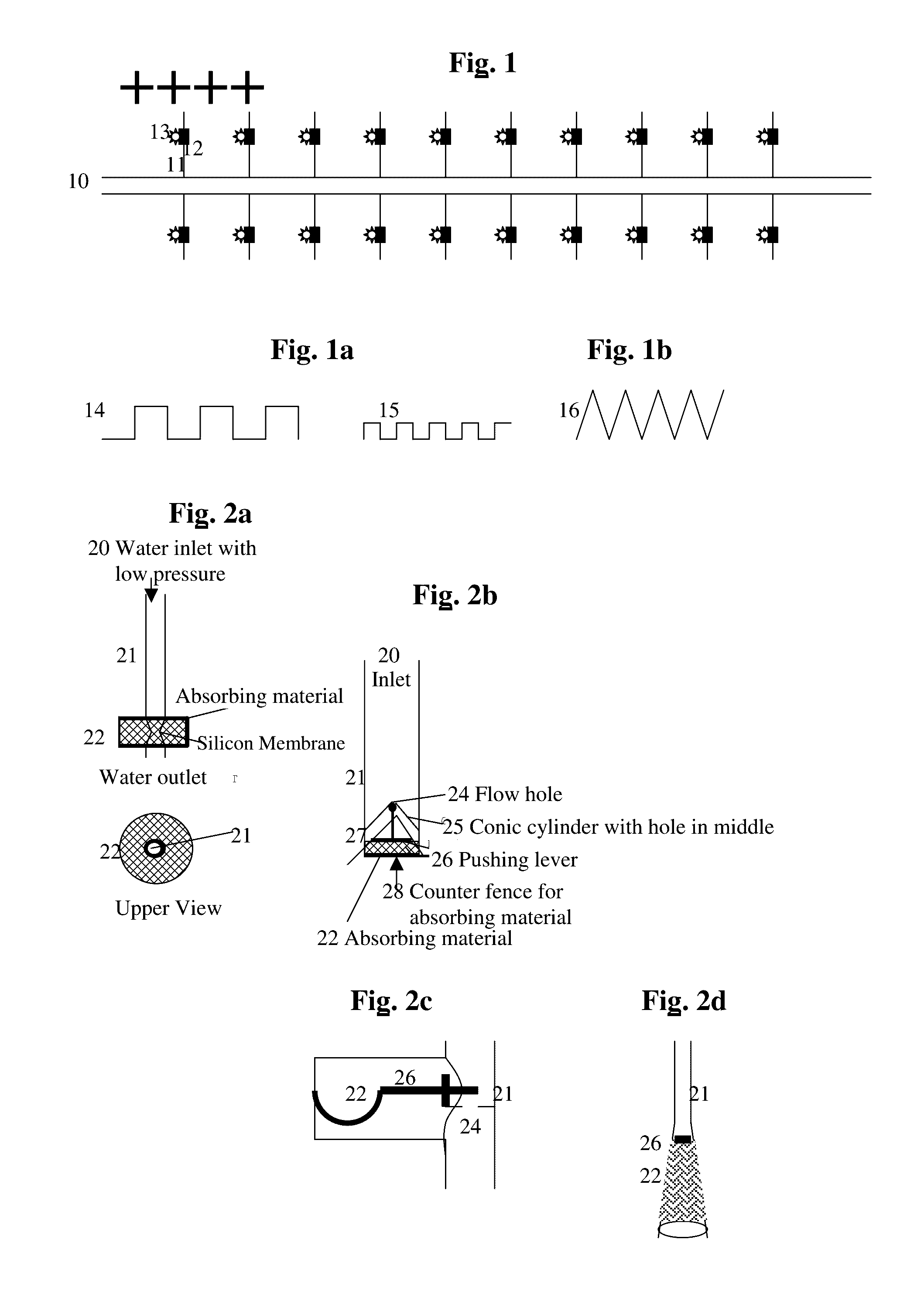
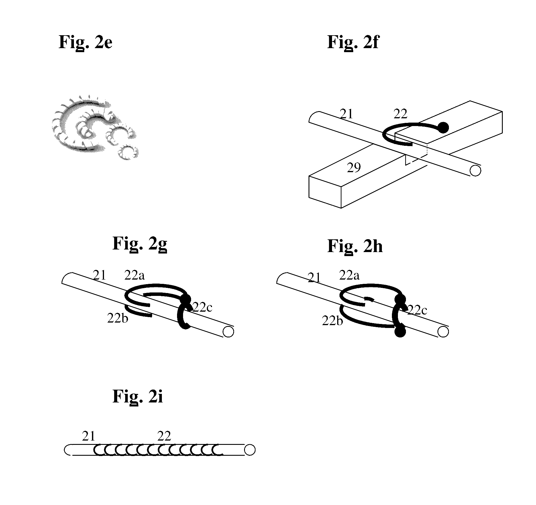
[0026]Referring to FIGS. 1 & 1a-b, we show a top-view illustration of a preferable general configuration of a main pipe (10) with sufficient water pressure (such as for example 1 or a few atmospheres) which extends into smaller channels that go for example sideways (11) with a preferably much lower pressure that are preferably each controlled by its own cheap humidity sensor (13) and cheap valve (12). Each such side-channel can go for example to an individual plant, or to a preferably small area surrounding a number of plants, as desired by the user. This way, the valve (12) that is needed to control each of these small channels (11) needs much less force and therefore can be much cheaper than an ordinary electronic faucet (solenoid), which typically contains a motor and is designed to deal with much higher pressures. Preferably the sensors are not too close to the end of t...


PUM


Abstract

The present invention provides an irrigation system with cheap humidity sensors and cheap automatic faucets preferably by using at the end nodes of the system low water pressure, so that much less force is needed to open and close the local waterway, and then either using simple electrical valves that do not require engines, or using for example mechanical sensors based on a bi-material of two or more materials which expand differently when they become wet, thus converting the difference of the expansion into convenient movement. Another possible variation, instead of mechanical sensors and valves, is to use for example a preferably synthetic material that tends to behave like a normal root preferably at the edge of each side channel, so that the “root” counter-balances the water supply and reaches equilibrium with it when the soil becomes wet enough, based preferably on asymmetric capillary materials.

Description

[0001]This patent application is a Continuation-In-Part of U.S. application Ser. No. 10 / 937,750 of Sep. 10, 2004, which is a CIP of PCT application PCT / IL 03 / 00195 of Mar. 10, 2003, hereby incorporated by reference in its entirety (which claims priority from Israeli application 148586 of Mar. 10, 2002, hereby incorporated by reference in its entirety, and also claims benefit and priorities from the following US provisional applications, hereby incorporated by reference in their entireties: 60 / 374,312 of Apr. 16, 2002, 60 / 403,610 of Aug. 12, 2002, 60 / 417,677 of Oct. 7, 2002), and which also claims priority from Canadian application 2,446,843 of Oct. 27, 2003.[0002]Therefore, priority and benefit is claimed from all of the above mentioned applications, and all of them are hereby incorporated by reference in their entireties.BACKGROUND OF THE INVENTION[0003]Field of the Invention[0004]The present invention relates to automatic irrigation with humidity sensors, and more specifically to ...

Claims


Application Information

Patent Timeline
Patent Type & Authority Patents(United States)
IPC IPC(8): B05B15/00A01G25/16A01G27/00
CPCA01G25/167A01G27/005
Inventor MAYER, YARONBAUR, AL J. C.GADASSI, HAIM
Owner MAYER BATYA BARHON
Why Eureka
Try Eureka