

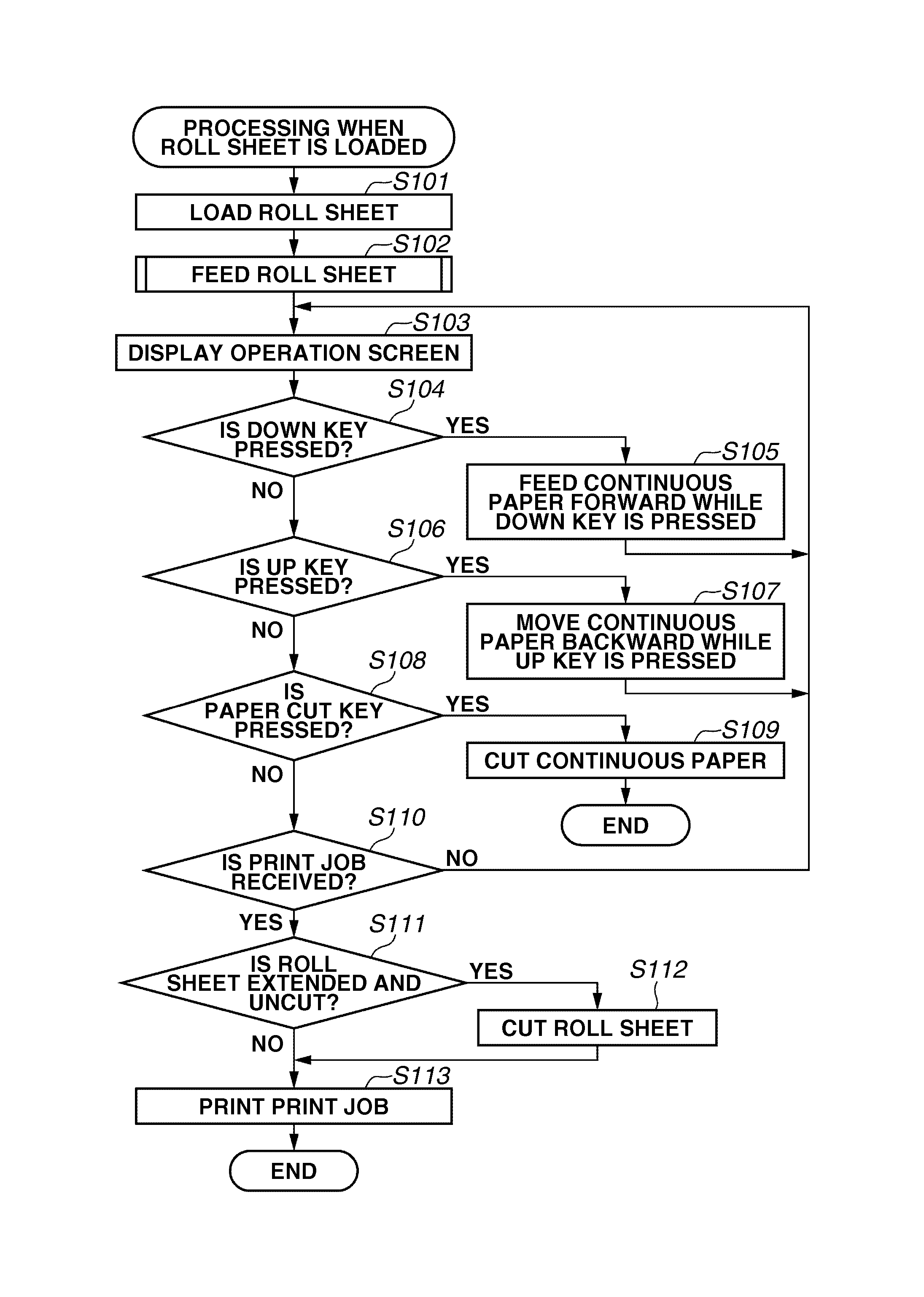
Printing apparatus with cut unit configured to cut a sheet according to an operator's instructions
a technology of printing apparatus and operator's instruction, applied in printing, metal working apparatus, thin material processing, etc., can solve the problems of reducing print quality, printing on stained paper, and scratching or fingerprinting of the leading edg
- Summary
- Abstract
- Description
- Claims
- Application Information
AI Technical Summary
Benefits of technology
Problems solved by technology
Method used
Image

Examples
Embodiment Construction
[0024]Various exemplary embodiments, features, and aspects of the invention will be described in detail below with reference to the drawings.
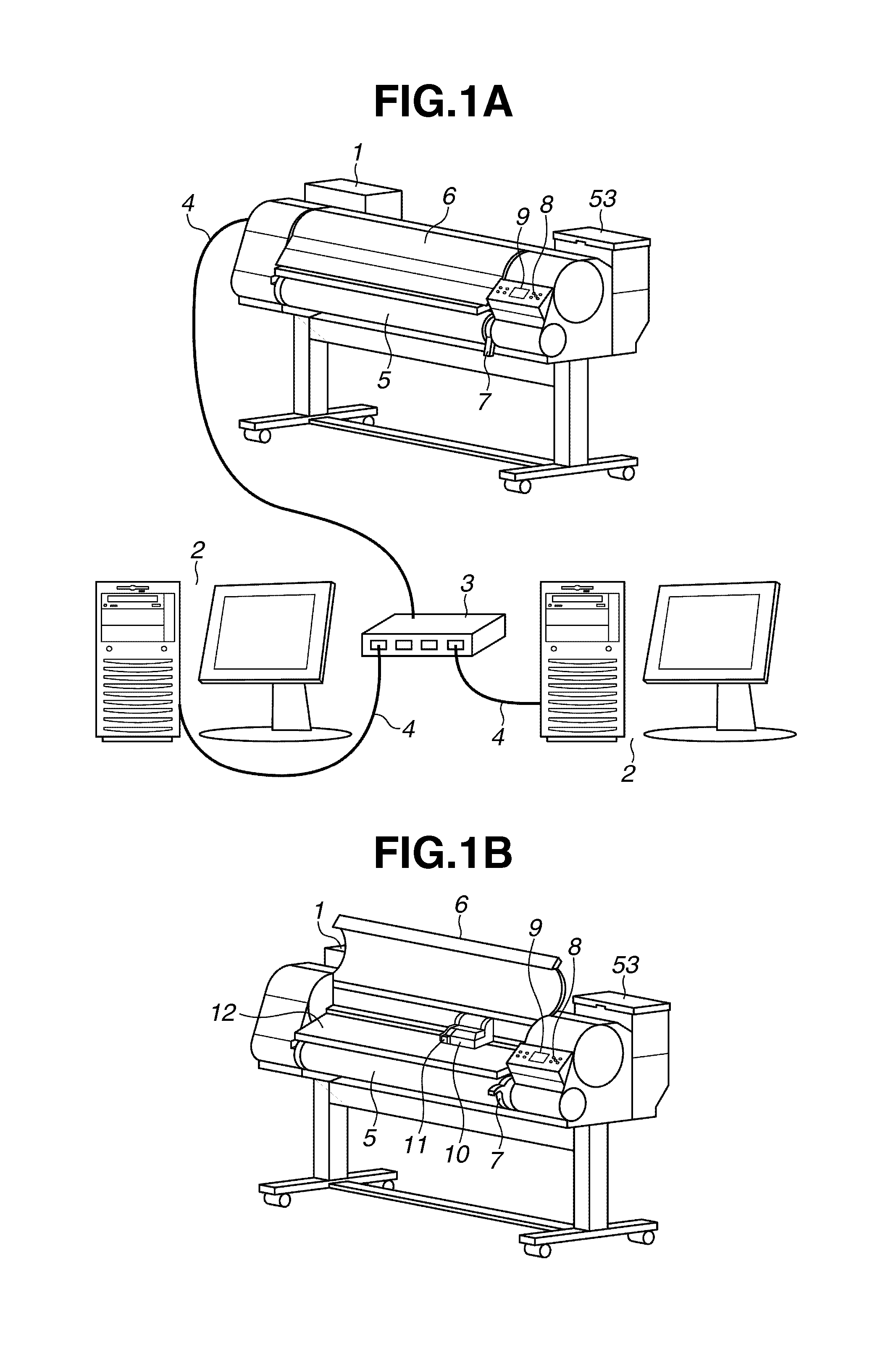
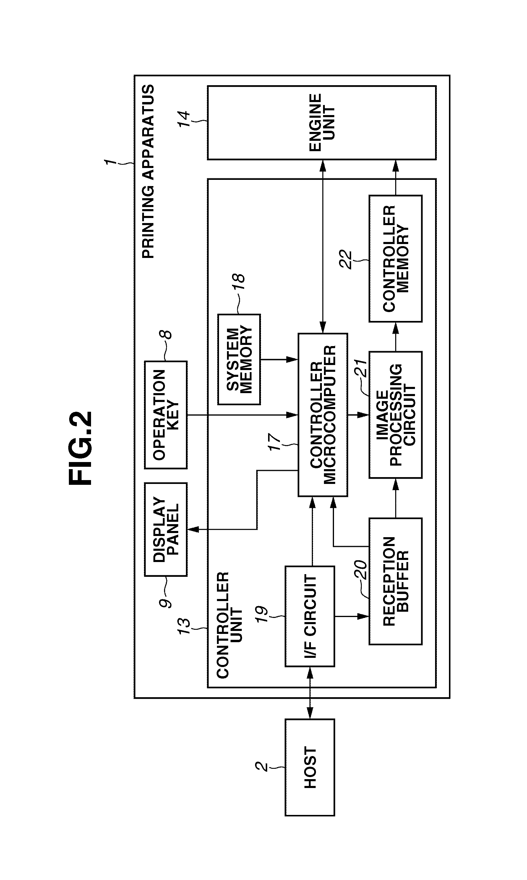
[0025]A first exemplary embodiment will be described. FIG. 1A is a diagram illustrating a printing apparatus according to the first exemplary embodiment of the present invention. In the diagram, the printing apparatus 1 performs printing on a print sheet based on information input from outside and / or information previously stored inside. A plurality of host computers (hereinafter, referred to as hosts) 2 are connected to the printing apparatus 1 through a network hub 3 and network cables 4. The hosts 2 transfer print data and information for controlling the printing apparatus 1 (hereinafter, referred to as a print job) to the printing apparatus 1. A roll sheet 5 is a continuous long sheet (recording medium) that is wound in a roll shape. The loaded roll sheet 5 is rotatably supported by a support unit. A main cover 6 is opened when feeding a ro...
PUM
| Property | Measurement | Unit |
|---|---|---|
| time | aaaaa | aaaaa |
| conveyance distance | aaaaa | aaaaa |
| length | aaaaa | aaaaa |
Abstract
Description
Claims
Application Information