
Nano-sensors for oil and gas reservoir characterization

a technology of oil and gas reservoirs and nanosensors, which is applied in the direction of instruments, fluid removal, borehole/well accessories, etc., can solve the problems of limiting the stability of fluorescent materials for reservoir imaging, the use of oil reserves, and the rapid depletion of world's easily accessible oil reserves, so as to achieve significant freedom of surface chemistry and stability

Active Publication Date: 2016-11-15
NEDERLANDSE ORG VOOR TOEGEPAST NATUURWETENSCHAPPELIJK ONDERZOEK TNO
View PDF7 Cites 3 Cited by
  • Summary
  • Abstract
  • Description
  • Claims
  • Application Information

AI Technical Summary

Benefits of technology

[0008]Another and relative new type of “nano” particles are the so-called noble metal clusters. Their bright optical behavior, which is size-tunable, is to a certain extent comparable to that of QDs.17 Their inert inorganic nature together with their relatively high chemical stability and solution process ability makes these noble metal clusters an interesting material to combine with the earlier discussed QDs in a mixed sensor for reservoir imaging. Water-dispersed nano-sensors are compatible with the commonly applied technique of water flooding and therefore an ideal starting point, as its infrastructure is readily available throughout the oil and gas industry for enhanced oil recovery.3 Extended information about the specific chemical and physical conditions within the reservoir is beneficial to optimize secondary oil production.
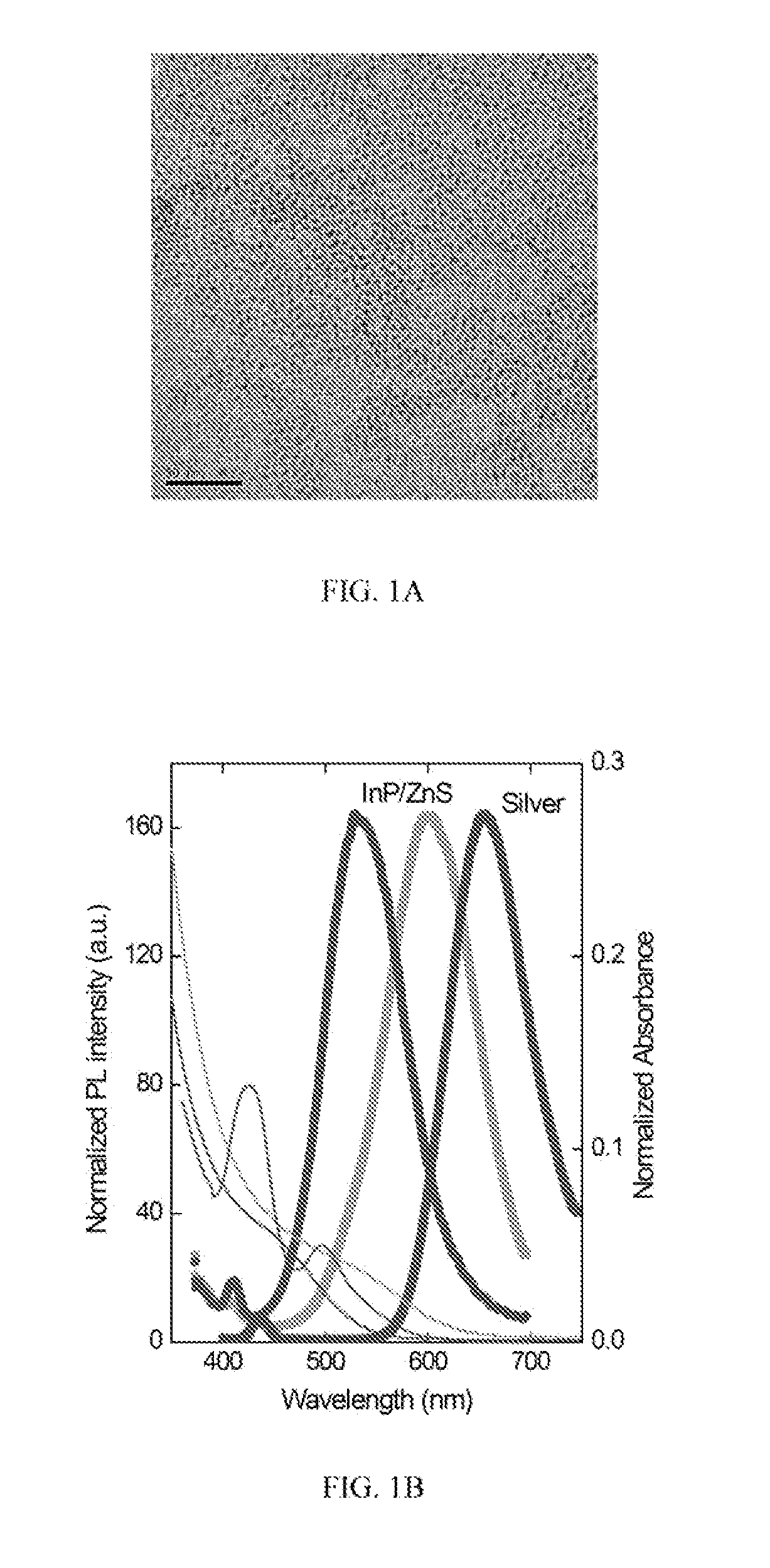
[0011]QDs and silver clusters are described herein as a class of materials for applications as luminescent probes with dedicated sensor functionalities for reservoir imaging, exhibiting stability and a significant freedom for surface chemistry.

Problems solved by technology

As a result of the ever expanding demand for energy, the world's easily accessible oil reserves become swiftly depleted.
The limitation of the commonly applied isotope tracers is that they primarily provide information on flow characteristics, and often do not possess any physical and chemical sensor functionality.10 In addition, a significant number of reported tracers consist of either toxic compounds or radioactive nuclides.8,9 This limits their use due to health, safety, environmental, and legislation issues.
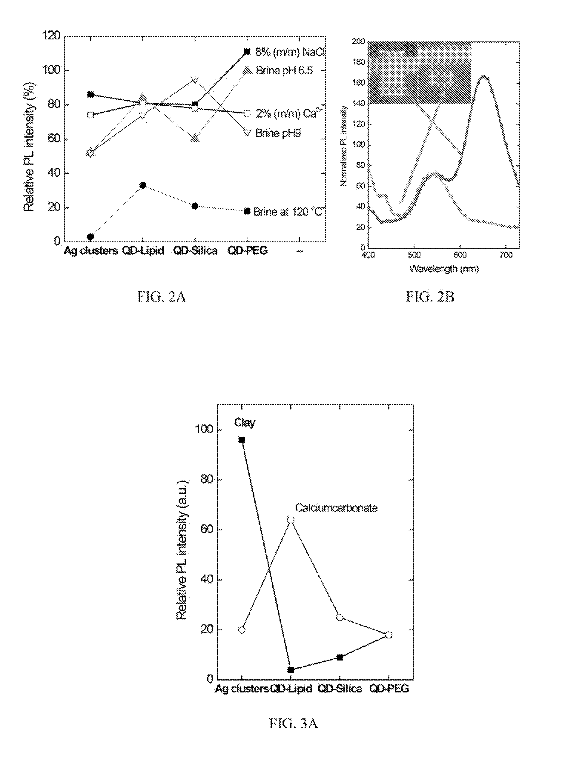
The challenging reservoir conditions (e.g., high salinity, high pH, and temperature) have often been found as the limiting factor on the stability of fluorescent materials for reservoir imaging.

Method used


Image

  • Nano-sensors for oil and gas reservoir characterization
  • Nano-sensors for oil and gas reservoir characterization
  • Nano-sensors for oil and gas reservoir characterization

Examples


Embodiment Construction

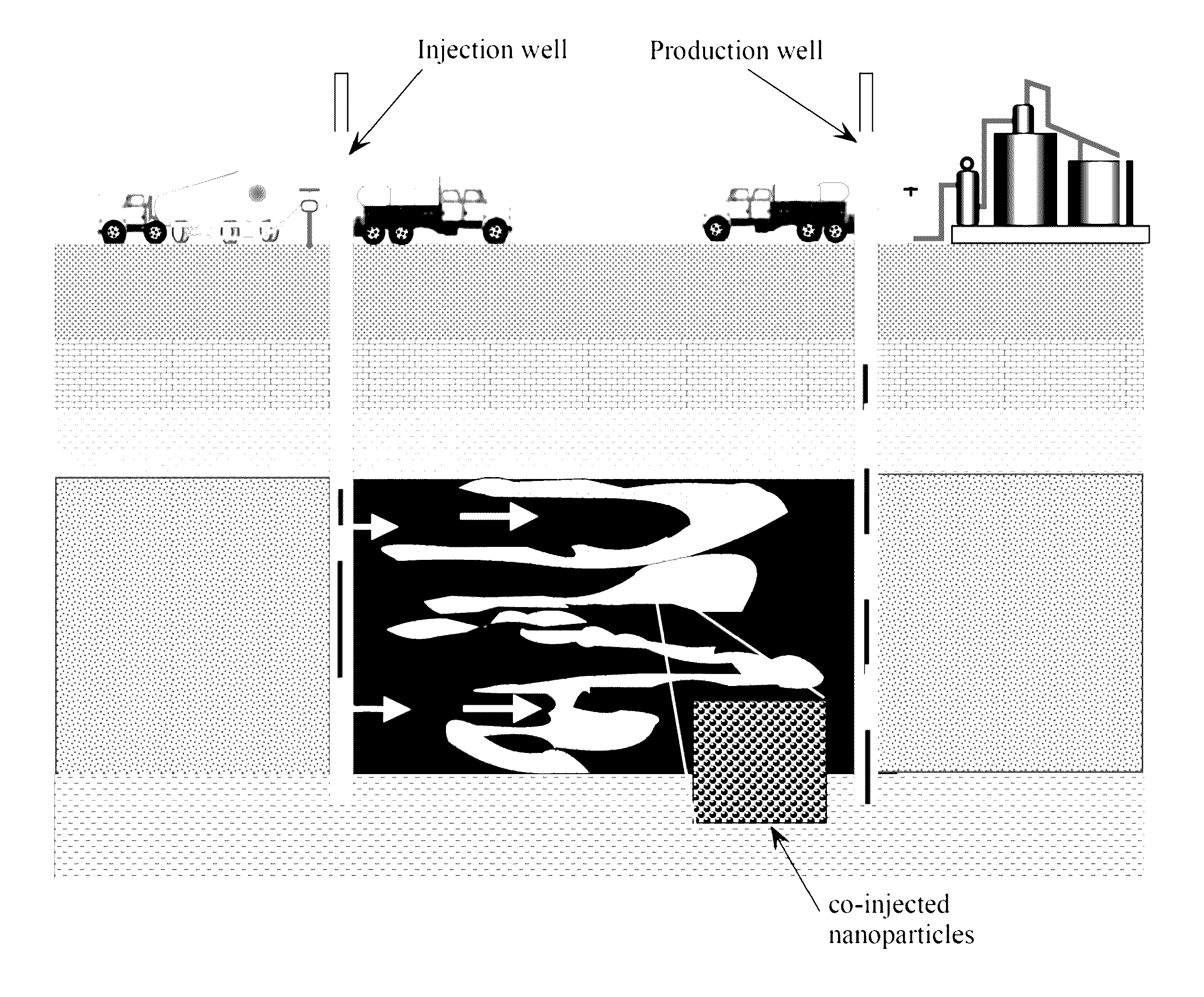
[0028]Referring to FIG. 9, in embodiments of the present invention, QDs and noble metal clusters are implemented as a nano-sensor with specific functionality customized for reservoir management in a water flooding process. Embodiments of the present invention develop a nano-sensor composition based on InP / ZnS core shell QDs and atomic silver clusters. As these materials lay within the size range of 1-20 nm, there is no size limitation with respect to the pore size of the reservoir formation.12 Due to the differences in surface chemistry of the nanomaterials, they experience different reactions depending on the specific local conditions. The nano-sensors may be injected into a formation at an injection well, including accompanying a water flooding process. After recovery of the nano-sensors from the production well, they are analyzed and the chemical and optical properties are compared to the initial situation before injection. The differences between both measurements provide a uniq...


PUM


Abstract

Enhanced oil recovery becomes increasingly important in satisfying the growing demand for fossil fuel. The efficiency of secondary recovery processes like water flooding is however largely influenced by the rock characteristics, fluid characteristics, chemistry and physics. For development of the full potential of secondary oil recovery, it remains a challenge to obtain sufficient knowledge about the reservoir conditions. The present invention provides a novel water-dispersed, nano-sensor composition based on. InP / ZnS quantum dots (“QDs”) and atomic silver clusters, which exhibit a bright visible fluorescence combined with dedicated sensor functionalities. The QD and silver nano-sensors were tested in simulated reservoir conditions to determine their selected functionality to these reservoir conditions. The developed nano-sensors showed improved sensor functionalities towards pH, temperature, and subterranean reservoir rock, such, as clay or limestone.

Description

[0001]This application claims priority to U.S. Provisional Patent Application Ser. No. 61 / 624,346 filed Apr. 15, 2012, which is hereby incorporated by reference herein.BACKGROUND AND SUMMARY[0002]As a result of the ever expanding demand for energy, the world's easily accessible oil reserves become swiftly depleted. The oil and gas industry today has a typical recovery of hydrocarbons with value of 30-40%,1,2 which indicates that the majority of the existing oil remains trapped in the pores of the oil bearing porous media. An increase in recovery efficiency (up to 60-80%)1 will therefore be a key factor for meeting the increasing energy demands. To this end, there is a need for new and more sophisticated mapping and production techniques.[0003]Injection of water, also referred to as water flooding,3 is commonly applied to produce so-called secondary oil, resulting in an increase of the total recovery efficiency up to 50%.4 The recovery results of a water flooding process is largely i...

Claims


Application Information

Patent Timeline
Patent Type & Authority Patents(United States)
IPC IPC(8): E21B43/16G01V9/00E21B41/00
CPCE21B43/16E21B41/0092G01V9/00
Inventor TURKENBURG, DANIEL H.CHIN, PATRICK T. K.FISCHER, RUDOLF H.
Owner NEDERLANDSE ORG VOOR TOEGEPAST NATUURWETENSCHAPPELIJK ONDERZOEK TNO
Learn More