Large long cone-shaped horn cylinder part extruding forming method

A technology of extrusion forming and horn, which is applied to other manufacturing equipment/tools, metal processing equipment, manufacturing tools, etc., can solve the problems of insufficient punch strength and breakage, and achieve the effect of not easy to break

Inactive Publication Date: 2014-02-12
ZHONGBEI UNIV
View PDF4 Cites 14 Cited by
  • Summary
  • Abstract
  • Description
  • Claims
  • Application Information

AI Technical Summary

Problems solved by technology

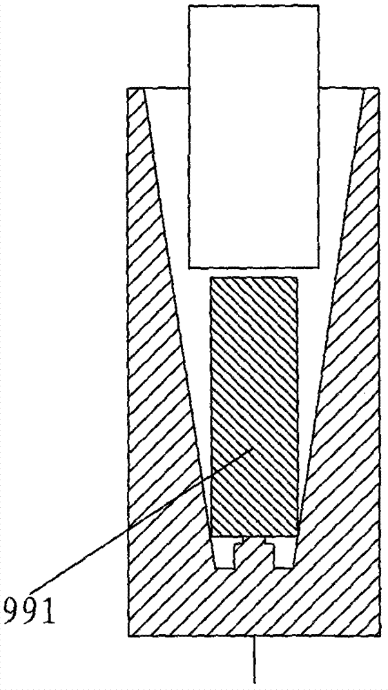
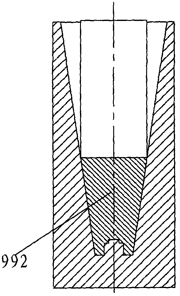
like Figure 2 to Figure 5 As shown, in the traditional extrusion method, the blank piece 991 is upset to form the upset piece 992, and then the punch 30 is used to extrude along the wall of the upset piece 992, the material will flow in the opposite direction of the punch 30, and the punch The deeper the 30 is squeezed downward, the area of ​​the cylinder wall increases upwards, and the friction force along the direction of the cylinder wall increases, and as the area of ​​the cylinder wall grows, there is no lubricant between these new areas and the surfaces of the male die 30 and the concave die 40 , the friction coefficient increases, which is about 0.5-1, which is also a factor of friction increase; in addition, as the area grows, the punch 30 is subjected to material deformation resistance in the vertical upward direction component force increases, and the result is easy to bring The reason is that the strength of the punch is not enough and the phenomenon of breaking occurs. Secondly, for the cone cylinder of φ600*1400, the direct extrusion pressure reaches 6000 tons. Therefore, it is necessary to adopt a new special mold structure and a new special method to solve the problem of the cone cylinder of Extruded on a 1000-ton extrusion machine

Method used


Image

  • Large long cone-shaped horn cylinder part extruding forming method
  • Large long cone-shaped horn cylinder part extruding forming method
  • Large long cone-shaped horn cylinder part extruding forming method

Examples


Embodiment Construction

[0043] The present invention will be further described below in conjunction with accompanying drawings and examples.

[0044] A method for extrusion forming of large-scale long tapered trumpet parts, sawing and blanking --- upsetting pre-forming --- primary extrusion of hemispherical bottom straight wall tube --- secondary flaring, shaping, extrusion cone barrel, as follows:

[0045] (1), sawing blanking---upsetting preforming, such as Figure 6 , Figure 7 As shown, using isothermal extrusion of magnesium alloy or aluminum alloy, the heating temperature of the blank 99 is 350°-400°, the heating temperature of the upsetting die 401 is 420°, and the upsetting die 401 is put into the upsetting die 401 to use the upsetting punch punch 31 Carry out upsetting, the mold cavity 402 of upsetting die 401 and long taper trumpet part 9 (as Figure 14 Shown) the shape of the upper half is consistent, forming an upsetting blank 995 (such as Figure 7 shown);

[0046] (2) Extrude the h...


PUM

PropertyMeasurementUnit
friction coefficientaaaaaaaaaa

Abstract

The invention discloses a large long cone-shaped horn cylinder part extruding forming method. The large long cone-shaped horn cylinder part extruding forming method includes the following steps that firstly, saw cutting, blanking and upsetting pre-forming are performed, a blank is put into an upsetting concave mold and an upsetting convex mold puncher chip is used for carrying out upsetting and an upsetting blank is formed; secondly, a semi-spherical bottom straight wall cylinder is extruded in a one-time mode and a pre-forming convex mold puncher chip is used for replacing the upsetting convex mold puncher chip and the upsetting blank is extruded by the semi-spherical bottom straight wall cylinder to form a pre-formed part; thirdly, secondary flaring, reshaping and cone-shaped cylinder extruding are performed, the finally-formed convex mold puncher chip is used for replacing a pre-forming convex mold puncher chip, the upsetting concave mold is replaced by a finally-forming concave mold, the pre-formed part suspends when being placed in a mold cavity of the finally- forming concave mold and the head portion of a first section rod body of the finally- forming convex mold puncher chip directly acts on a semi-spherical bottom of a center cavity of the pre-formed part. When extruding is finally finished, a third section rod body of the finally-forming convex mold puncher chip is in contact with a port of the center cavity of the pre-formed part. The cone face of the third section rod body is used for finishing flaring, shaping and cone-shaped cylinder extruding.

Description

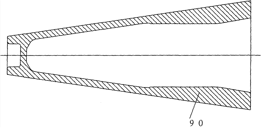
technical field [0001] The invention belongs to metal extrusion forming technology, in particular to an extrusion forming method of a large-scale long tapered horn tube. Background technique [0002] Such as figure 1 The large long tapered horn tube part 90 shown has a size of φ600*1400mm, which belongs to a large part. In addition to being tapered outside, its inner cavity is also double tapered. Such as Figure 2 to Figure 5 As shown, in the traditional extrusion method, the blank piece 991 is upset to form the upset piece 992, and then the punch 30 is used to extrude along the wall of the upset piece 992, and the material will flow in the opposite direction of the movement of the punch 30, and the punch The deeper the 30 is squeezed downward, the larger the area of ​​the cylinder wall is, and the friction force along the direction of the cylinder wall increases, and as the area of ​​the cylinder wall grows, there is no lubricant between these newly formed areas and the ...

Claims


Application Information

Patent Timeline
Patent Type & Authority Applications(China)
IPC IPC(8): B23P23/02B21C23/04
CPCB21C23/205B21J5/02B21J5/08
Inventor 张治民李国俊李旭斌王强于建民贾杨谢志平路光
Owner ZHONGBEI UNIV
Why Eureka
Try Eureka