Electric motor

a technology of electric motors and motors, applied in the direction of dynamo-electric components, dynamo-electric machines, structural associations, etc., can solve the problems of normal miniaturization, reduce the order of motors, reduce the number of slots, and reduce the noise of high pitch

Active Publication Date: 2016-11-15
MITSUBA CORP
View PDF10 Cites 1 Cited by
  • Summary
  • Abstract
  • Description
  • Claims
  • Application Information

AI Technical Summary

Benefits of technology

[0026]According to the present invention, since the number of slots can be reduced without degrading motor performance, an order of the motor can be reduced. For this reason, high pitch noise can be prevented upon rotation of the motor at a high speed.
[0027]In addition, as the number of slots is reduced, the shape of the armature core can be simplified and productivity of the armature can be increased. Further, as the number of slots is reduced, a size of each slot can be set to be large. For this reason, the number of times the coil is wound on each tooth can be set to be large, and as a result, the armature core can be reduced in size and weight.
[0028]Further, as the number of segments is set to be larger three or more times the number of slots, the number of segments per one pole pair can be increased. For this reason, a voltage between the segments can be reduced, and rectification can be improved. In addition, since the number of effective conductors of the coil per one segment is reduced, it is possible to easily cope with a variation in speed due to the high speed brush.
[0029]Further, since the coil is wound on the teeth through an intensive winding method, a space factor of the coil can be improved in comparison with the case in which the coil is wound through the distributed winding method as described in the related art. Furthermore, overlapping of the coil ends can be reduced. For this reason, wire rod cost of the coil can be reduced, and an inexpensive electric motor can be provided. In addition, when the motor performance is the same, the armature core can be reduced in size and the shaft can be reduced in length.

Problems solved by technology

However, the motor such as a wiper motor or the like mounted on the vehicle normally needs to be miniaturized due to requirements of improvement of vehicle mountability or the like.

Method used


Image

  • Electric motor
  • Electric motor
  • Electric motor

Examples


first embodiment

(Reduction Motor)

[0041]Next, a first embodiment of the present invention will be described with reference to FIGS. 1 to 5.

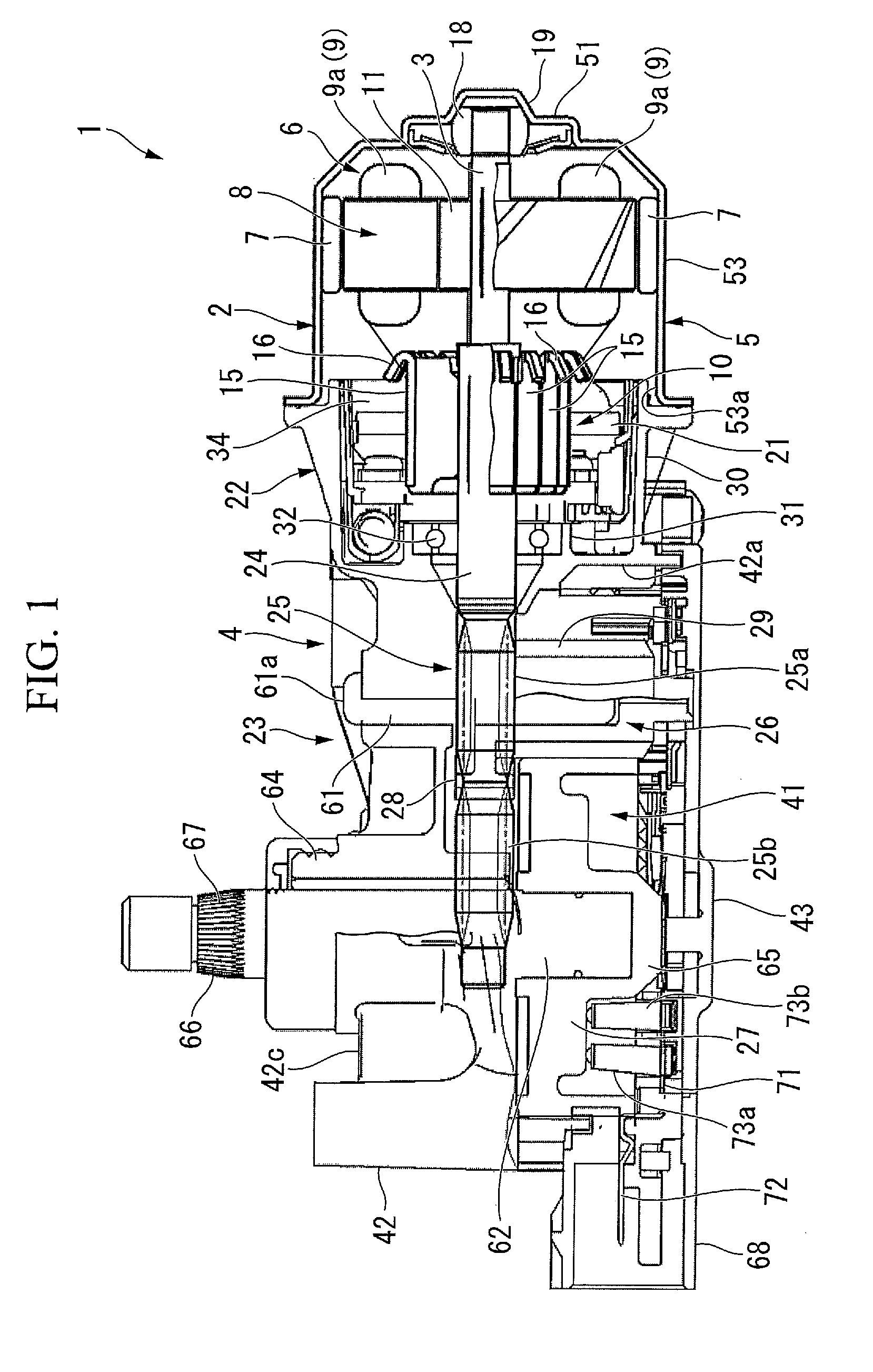
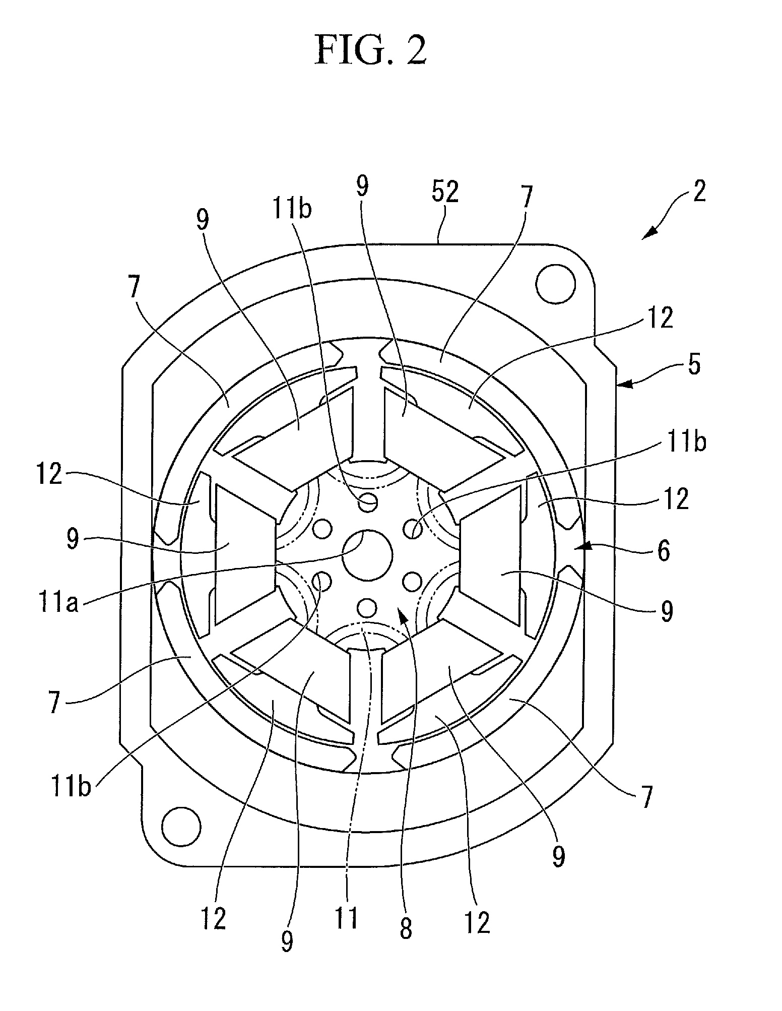
[0042]FIG. 1 is a longitudinal cross-sectional view of a reduction motor 1 to which an electric motor 2 according to the embodiment is applied. FIG. 2 is a plan view of the electric motor 2 when seen in an axial direction thereof.

[0043]As shown in FIGS. 1 and 2, the reduction motor 1 is a motor used to drive, for example, a wiper of an automobile. The reduction motor 1 includes the electric motor 2, and a speed reduction mechanism 4 connected to a rotary shaft 3 of the electric motor 2. The electric motor 2 has a tubular yoke 5 having a bottom section, and an armature 6 rotatably installed in the yoke 5.

[0044]A tubular section 53 of the yoke 5 is formed in a substantially tubular shape. A four-segment type permanent magnet 7 is disposed at an inner circumferential surface of the tubular section 53.

[0045]A bearing housing 19 protruding from a center in a radial di...

second embodiment

(Modified Example of Second Embodiment)

[0138]FIG. 9A is a perspective view of a holder stay 334. FIG. 9B is a side view of the holder stay 334.

[0139]That is, as shown in FIGS. 9A and 9B, only the brushes 221 (221a, 221b and 221c) are inserted into holder stay opening sections 114 formed in the holder stay 334. Then, a brush holder 336 configured to hold the brush 221 is installed at a surface of the holder stay 334 near the speed reduction mechanism 4 (a left side of FIG. 9B) to cover the holder stay opening section 114.

[0140]In addition, a pair of engaging claws 120 is formed opposite to each other in the circumferential direction at an opening edge of the brush holder 336. In addition, a slit 121 that can engage with the engaging claw 120 is formed in the holder stay 334. According to the above-mentioned configuration, the brush holder 336 is fixed to the holder stay 334.

[0141]Even in the case described above, the same effect as of the above-mentioned second embodiment can be exhi...


PUM


Abstract

An electric motor includes a yoke having a plurality of magnetic poles, a rotary shaft, an armature core (8) attached to the rotary shaft, the armature core (8) having a plurality of teeth (12) and slots (13), an armature coil (9) wound on the teeth (12) through an intensive winding method, a commutator having a plurality of segments (15) installed at the rotary shaft and disposed in a circumferential direction, a low speed brush (21a) and a high speed brush (21b) configured to supply power to the armature coil (9) via the segments (15), and a common brush (21c) commonly used in these brushes, wherein, when n is a natural number of 3 or more, a ratio of the numbers of magnetic poles, slots (13), and segments (15) is set to 2:3:3n.

Description

TECHNICAL FIELD[0001]The present invention relates to an electric motor mounted on, for example, a vehicle.[0002]Priority is claimed on Japanese Patent Application Nos. 2011-164304, filed Jul. 27, 2011, and 2011-250721, filed Nov. 16, 2011, the contents of which are incorporated herein by reference.BACKGROUND ART[0003]For example, as a wiper motor for an automobile, a 3-brush type motor that can switch a rotational speed may be used. In such a motor, an armature on which an armature coil is wound is rotatably disposed inside a cylindrical yoke including a plurality of magnetic poles installed at an inner circumferential surface thereof. The armature has the armature core fitted into and fixed to a rotary shaft from the outside thereof. A slot elongated in an axial direction is formed in the armature core. A plurality of coil in which windings are wound at predetermined intervals according to a distributed winding method are formed in the slot. Each coil is electrically connected to ...

Claims


Application Information

Patent Timeline
Patent Type & Authority Patents(United States)
IPC IPC(8): H02K13/00H02K13/04H02K23/04H02K5/14H02K23/30H02K11/02
CPCH02K13/04H02K5/148H02K23/04H02K23/30H02K11/026H02K2213/03
Inventor KAWASHIMA, YOSHICHIKATOKIZAKI, TEPPEI
Owner MITSUBA CORP
Why Eureka
Try Eureka