Photovoltaic mounting system and devices

a technology of mounting system and photovoltaic energy, applied in the direction of photovoltaic supports, heat collector mounting/supports, light and heating equipment, etc., can solve the problems of messy installation, a large amount of flashing, and a potential leakage point, so as to improve the sealing effect and improve the sealing

Active Publication Date: 2016-11-15
TESLA INC
View PDF56 Cites 21 Cited by
  • Summary
  • Abstract
  • Description
  • Claims
  • Application Information

AI Technical Summary

Benefits of technology

[0016]In various embodiments, such mounting systems can include an anchor base having a top surface with a recessed shoulder circumscribing the top opening of the through-hole. Such a configuration can provide a load path applied through a head of the mechanical fastener during tightening that extends through the base via the shoulder so as to reduce or eliminate loads applied to the carrier. Such embodiments can utilize a carrier formed of a plastic or thermoresin, while the anchor base is typically formed of a more rigid, higher strength material, such as a cast metal (e.g. aluminum or steel alloy).
[0018]In various embodiments, such mounting systems can include an anchor base having one or more pairs of alignment markers viewable by a user during mounting. The alignment markers correspond to outer bounds of the recessed cavity of the carrier so as to allow the user to visualize the eventual location of the chemical flashing formed within the cavity. Such a configuration allows positioning of the base over any secondary roof penetrations adjacent to the roof penetration through which the mechanical fastener extends.

Problems solved by technology

Although flashings cover up a lot of space, potentially covering mis-drilled or off-center pilot holes, flashings are relatively expensive because they require more metal than direct mounted solutions.
Each time a nail is removed, another potential leak point is created.
This can be messy for the installer, requires a separate large and bulky tool (e.g., caulk gun), and requires another product SKU to be stocked in the truck's inventory.
Moreover, there is no way to ensure that the installer remembers, or even he does remember, that he actually applies caulk or sealant to the lag holes.

Method used


Image

  • Photovoltaic mounting system and devices
  • Photovoltaic mounting system and devices
  • Photovoltaic mounting system and devices

Examples


Embodiment Construction

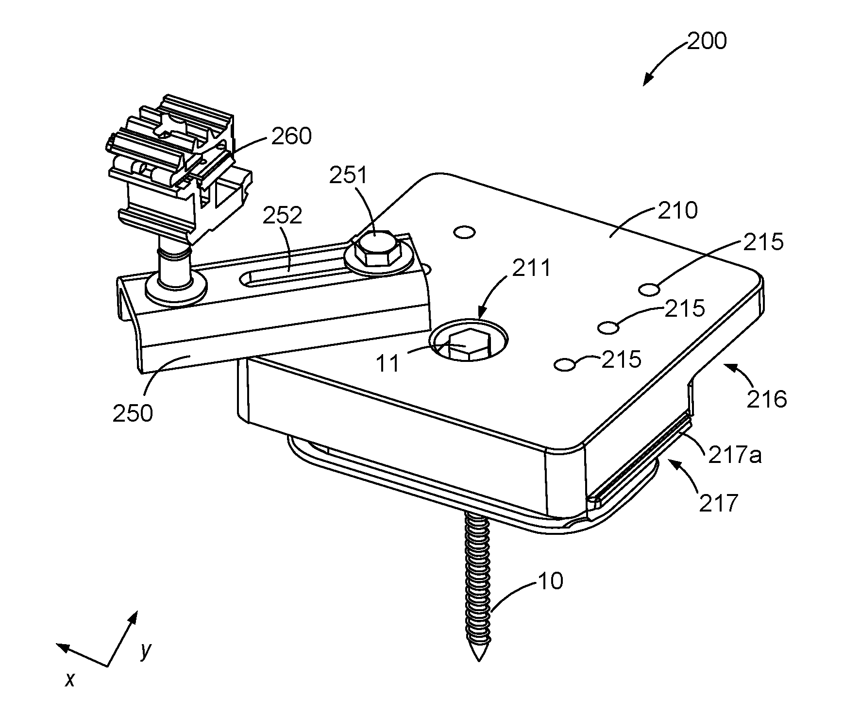
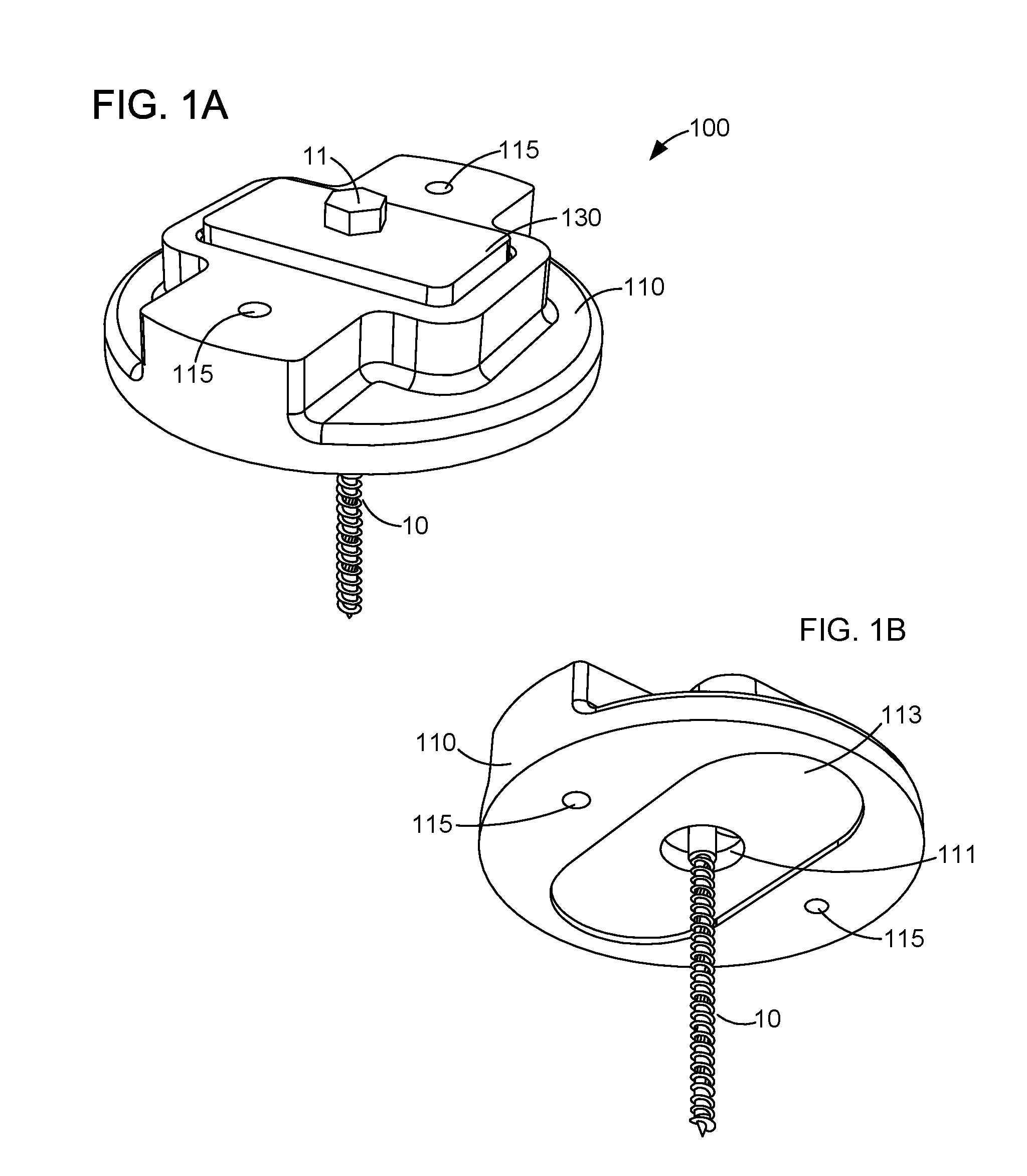
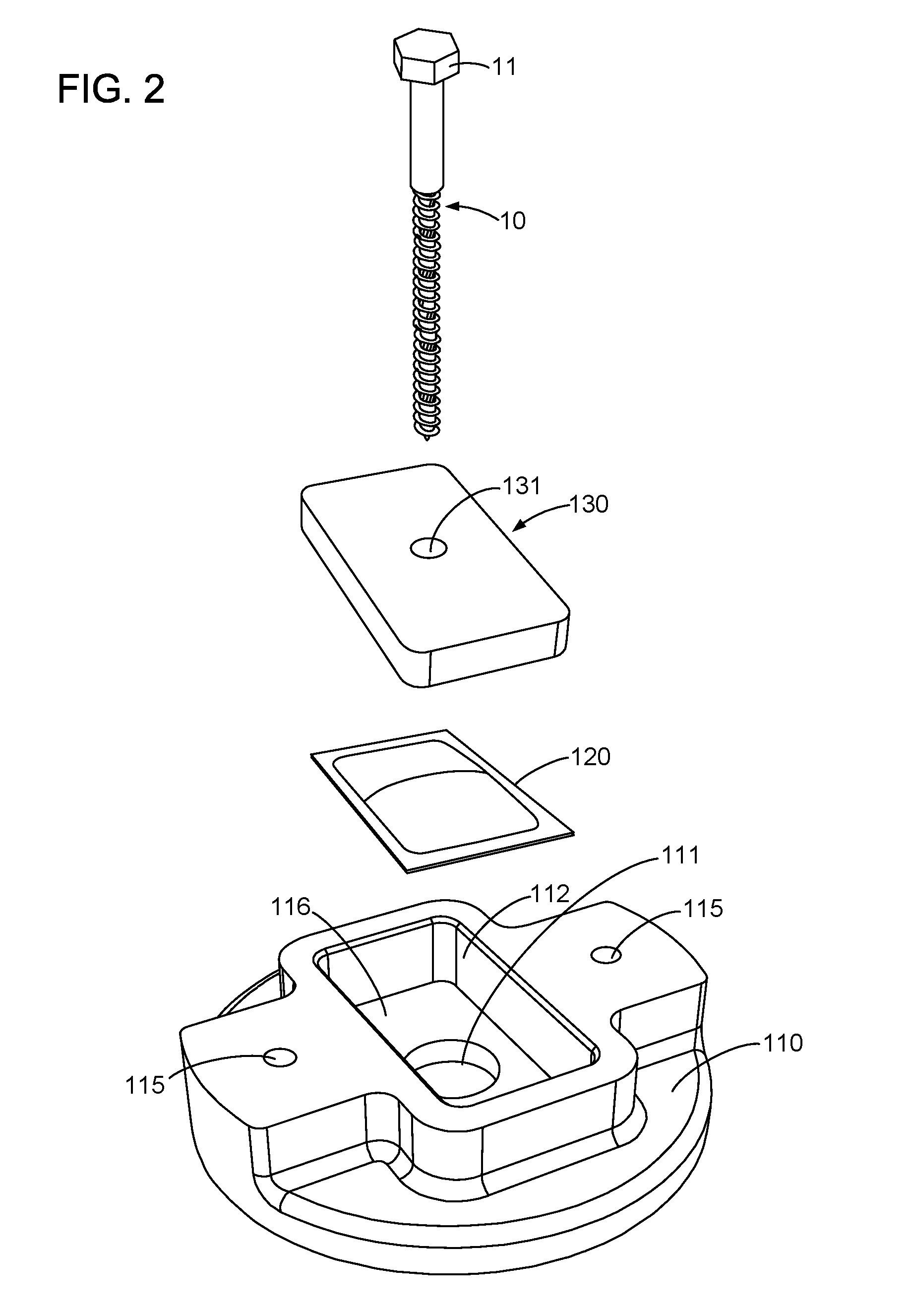
[0026]The present invention seeks to ameliorate some if not all of the shortcomings of the prior art with a photovoltaic mounting system that includes a sealant reservoir and injector mechanism that provides improved direction control of sealant injection as well as improved control over containment of injected sealant around a lag hole of a lag bolt torqued down to attach the photovoltaic mounting hardware to the roof. In various embodiments, the lag bolt may can engage a compressing plate or other structure that compresses a package containing sealant thereby forcing sealant to flow between the mounting hardware and the roof surface as the lag bolt is torqued down. In various embodiments, the photovoltaic mounting system may come pre-loaded with sealant injection package system so that the installer can guarantee that sealant is applied to every lag bolt, regardless of whether the installer intentionally does so. In other embodiments, the sealant reservoir is separable from the mo...


PUM


Abstract

Photovoltaic mounting systems having sealant injection system are provided herein. Such sealant injection systems provide directional control and containment of sealant flow providing improved sealing of roof penetrations of a mounted roof anchor. Such systems can include an anchor having a base and mechanical fastener and a sealant injection package, which includes a collapsible sealant injection reservoir and is adapted to provide directionally controlled release and containment of sealant upon tightening of the mechanical fastener into the roof surface. Such systems can include a sealant carrier that fits into an underside cavity of the anchor base and isolates the sealant injection package from anchoring load paths. The carrier can also define a flow path and sealant area in an underside recessed portion defining a cavity between the carrier and roof surface to provide a more uniform consistent sealant flow to form a chemical flashing about any roof penetration.

Description

CROSS REFERENCE TO RELATED APPLICATIONS[0001]This claims the benefit of priority of U.S. Provisional Patent Application No. 62 / 120,841 filed on Feb. 25, 2015, and U.S. Provisional Patent Application No. 62 / 260,178 filed on Nov. 25, 2015; each of which is incorporated herein by reference in its entirety.[0002]This is also related to U.S. patent application Ser. No. 14 / 949,820, filed Nov. 23, 2015, the disclosure of which is incorporated herein by reference in its entirety for all purposes.FIELD OF THE INVENTION[0003]The invention relates to photovoltaic energy generation mounting systems and more specifically to systems, devices and methods for installing photovoltaic modules on composition shingle roofs.BACKGROUND[0004]Although total market penetration of solar into the relevant base of potential customers remains relatively low in the United States (e.g. less than about one percent), residential and commercial solar installs have enjoyed double digit growth since the mid to late 20...

Claims


Application Information

Patent Timeline
Patent Type & Authority Patents(United States)
IPC IPC(8): H02S20/23
CPCH02S20/23F24S25/61F24S2025/021Y02B10/10Y02B10/20Y02E10/47Y02E10/50
Inventor SEERY, MARTINATCHLEY, BRIANBAUTISTA, GARRETALMY, CHARLES
Owner TESLA INC
Why Eureka
Try Eureka