Sensing system and sensing method

a sensing system and sensor technology, applied in the direction of dynamo-electric converter control, distance measurement, instruments, etc., can solve the problems of increasing and affecting the sensing effect of the sensor, so as to reduce the load on the drive mechanism

Active Publication Date: 2019-05-07
HONDA MOTOR CO LTD
View PDF13 Cites 0 Cited by
  • Summary
  • Abstract
  • Description
  • Claims
  • Application Information

AI Technical Summary

Benefits of technology

[0009]In view of the foregoing problems, it is an object of the present invention to provide a sensing system and a sensing method that can reduce or eliminate a load on a drive mechanism that rotationally moves a sensor, while keeping the sensor data acquisition density constant in at least some periods.
[0022]The moving angular velocity of the sensor thus becomes continuous in the respective periods, which reduces or eliminates the load on the drive mechanism.
[0024]As a result, according to the sensing system of the present invention, it is possible to reduce or eliminate the load on the drive mechanism that rotationally moves the sensor, while keeping the sensor data acquisition density constant in at least some periods.
[0026]According to the sensing system with this configuration, the angular velocity of the sensor changes smoothly at and around the time point at which the angle of the reference axis of the sensor becomes the first or second angle. It is therefore possible to reduce the load on the drive mechanism at the time point at which the transition direction of the sensor is changed.
[0028]According to the sensing system with this configuration, at least one of the first desired trajectory and the second desired trajectory is expressed by a circle. This ensures smooth changes of the angular velocity of the sensor in the first period and the second period. It is therefore possible to reduce the load on the drive mechanism in the first and second periods.

Problems solved by technology

At this time point tm, a drive mechanism responsible for moving the sensor may exceed the limit of its performance, or a considerable load may be applied to the drive mechanism.
With this control, however, the moving angular velocity of the sensor is not constant, as shown in FIG. 8D, making it difficult to keep the sensor data acquisition density constant.

Method used


Image

  • Sensing system and sensing method
  • Sensing system and sensing method
  • Sensing system and sensing method

Examples


Embodiment Construction

[0037]A sensing system 1 according to an embodiment of the present invention is mounted on a robot (not shown), and is configured to provide acquired sensor data to a control mechanism of the robot. Instead, the sensing system 1 may be mounted on a mobile body, such as a vehicle, or installed in a stationary object, such as a monitoring camera system in a building.

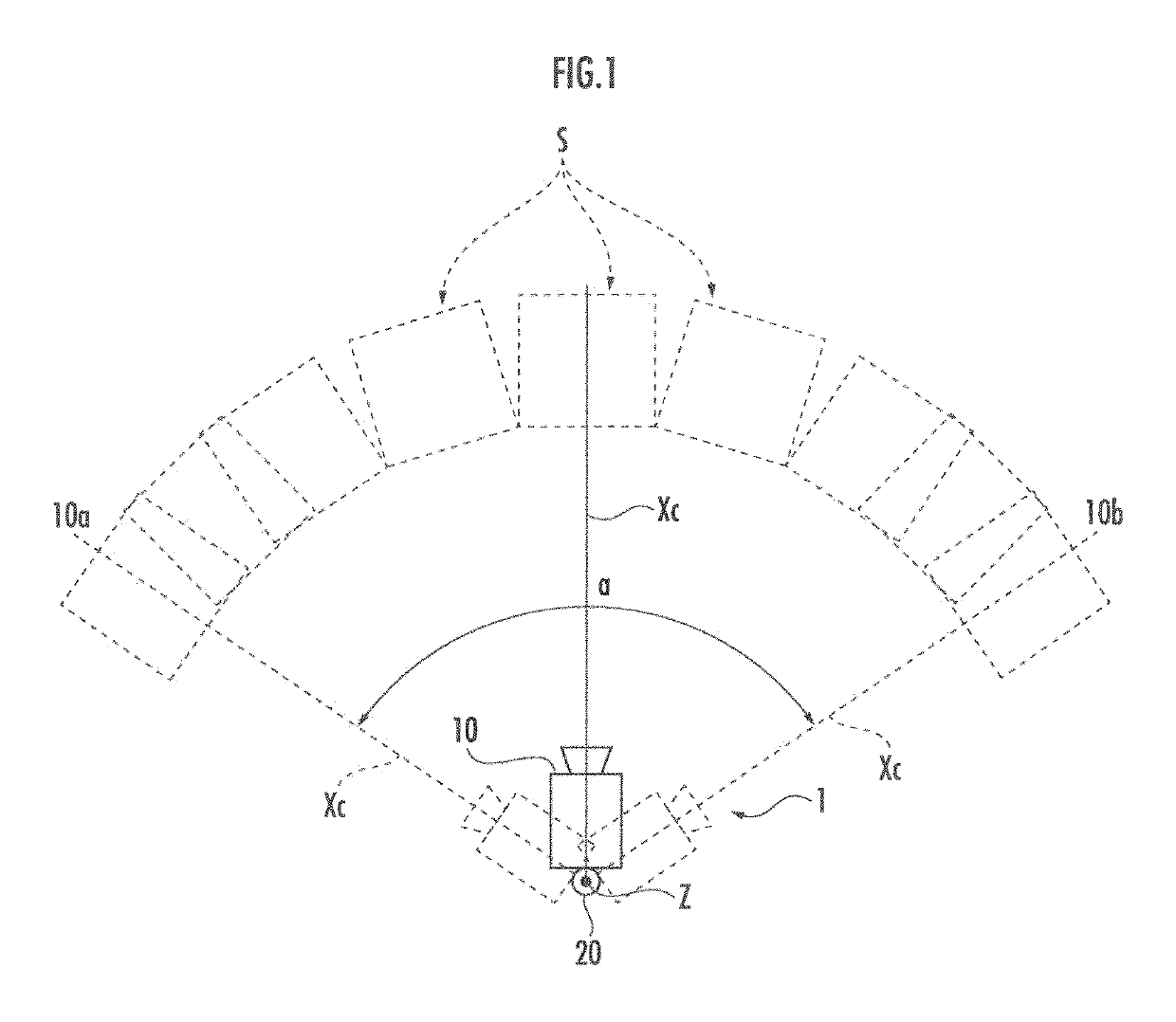
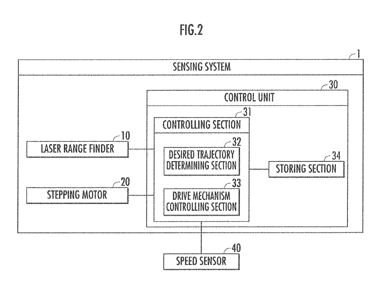
[0038]The sensing system 1, as shown in FIG. 1, includes a laser range finder 10, serving as a sensor, a stepping motor 20, serving as a drive mechanism, and a control unit 30 (see FIG. 2).

[0039]As shown in FIG. 1, the laser range finder 10 is configured to repeatedly measure distances (corresponding to the “information about surrounding space” in the present invention) by emitting laser light at prescribed time intervals, as its reference axis Xc (corresponding to the “reference axis” in the present invention; this corresponds to the optical axis of the laser range finder 10), for example, swings about a yaw axis Z (corre...


PUM


Abstract

Provided is a sensing system (1) in which a desired trajectory determining section (32) determines a first desired trajectory th(t) (where t<t1) whose first derivative is continuous, a second desired trajectory th(t) (where t2≤t<t3) whose first derivative is continuous, a third desired trajectory th(t) (where t1≤t<t2) configured with a common tangent line to the first and second desired trajectories, and a fourth desired trajectory th(t) (where t35≤t<t4) configured with a common tangent line to the second desired trajectory in the current-time cycle and a first desired trajectory in a next-time cycle. A drive mechanism controlling section (33) controls an operation of the drive mechanism so as to track the desired trajectories.

Description

BACKGROUND OF THE INVENTION[0001]Field of the Invention[0002]The present invention relates to a sensing system and a sensing method that use a sensor constituted to be rotatable.[0003]Description of the Related Art[0004]Sensing systems that recognize a surrounding environment using a sensor constituted to be rotatable are conventionally known.[0005]For example, as a type of such sensing systems, a three-dimensional measuring device that causes a CCD camera as a sensor to rotate in yaw and pitch directions and recognizes an object to be measured from image data picked up by the CCD camera has been proposed in Japanese Patent Application Laid-Open No. 2007-225434.SUMMARY OF THE INVENTION[0006]In the case of performing three-dimensional measurement using a sensor such as a camera or a laser range finder (LRF), it is desirable for the sensor data to be acquired with constant density. If the frequency of sensing by the sensor is constant, the sensor data acquisition density may be made c...

Claims


Application Information

Patent Timeline
Patent Type & Authority Patents(United States)
IPC IPC(8): G01C3/00H02P8/14G01S17/42G01S7/481H02P8/20H02P8/08G01C3/08G01S7/497H02P8/00
CPCG01C3/08G01S7/497G01S17/42H02P8/20H02P8/00H02P8/14G01S7/4817
Inventor KAMIOKA, TAKUMITANAKA, KENTA
Owner HONDA MOTOR CO LTD
Why Eureka
Try Eureka