Eureka AIR delivers breakthrough ideas for toughest innovation challenges, trusted by R&D personnel around the world.

Damping force variable valve assembly

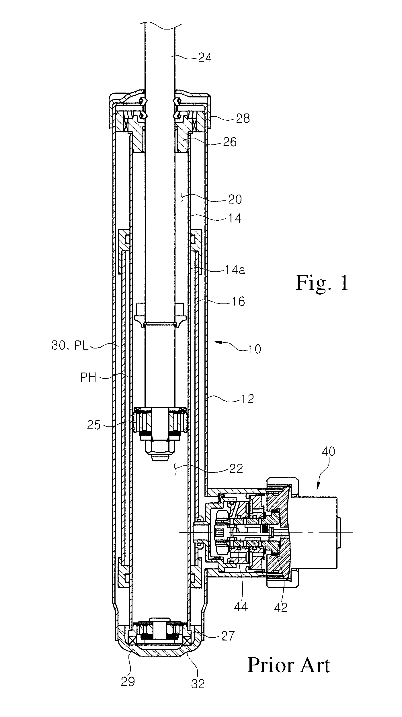
a technology of variable force and valve assembly, which is applied in the direction of shock absorbers, springs/dampers functional characteristics, vibration dampers, etc., can solve the problem that the small frequency of vibration transferred from the road surface cannot be damped, the flow rate of the working fluid flowing in the shock absorber is extremely low, and the movement speed of the working fluid is low or extremely low

Active Publication Date: 2016-11-29
HL MANDO CORP
View PDF4 Cites 4 Cited by
  • Summary
  • Abstract
  • Description
  • Claims
  • Application Information

AI Technical Summary

Benefits of technology

[0044]Hereinafter, exemplary embodiments of the present invention will be described in detail with reference to the accompanying drawings.

Problems solved by technology

However, in a case where an input (that is, shock) from a road surface is small and thus a moving speed of a working fluid is low or extremely low, a flow rate of the working fluid flowing in the shock absorber is extremely low.
Thus, a damping force is not generated in a low speed section and a small frequent vibration transferred from the road surface cannot be damped.
Accordingly, a hard damping force or dispersion may greatly occur and foreign substances may clog the slit, thus degrading operation performance.

Method used


Image

  • Damping force variable valve assembly
  • Damping force variable valve assembly
  • Damping force variable valve assembly

Examples


Embodiment Construction

[0044]Hereinafter, exemplary embodiments of the present invention will be described in detail with reference to the accompanying drawings.

[0045]The advantages and features of the present invention and methods for achieving them will become more apparent from the following embodiments that are described in detail in conjunction with the accompanying drawings.

[0046]However, the present invention is not limited to the following embodiments and may be embodied in various forms. These embodiments are provided so that this disclosure will be thorough and complete, and will fully convey the scope of the invention to those skilled in the art. The scope of the present invention is defined by the appended claims.

[0047]In addition, detailed descriptions of well-known technologies or the like will be omitted since they would unnecessarily obscure the subject matters of the present invention.

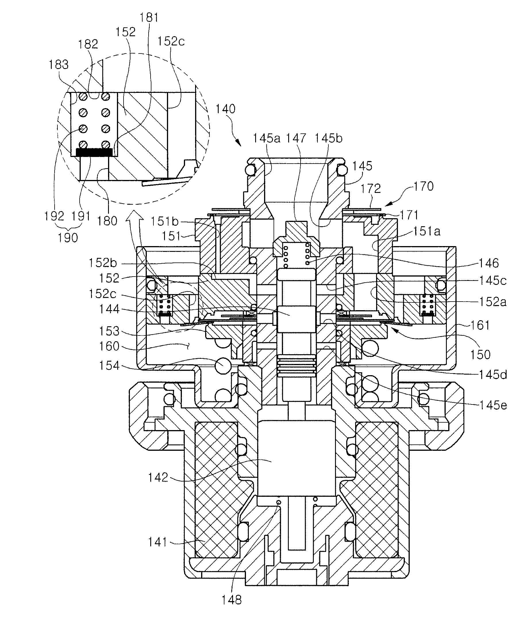
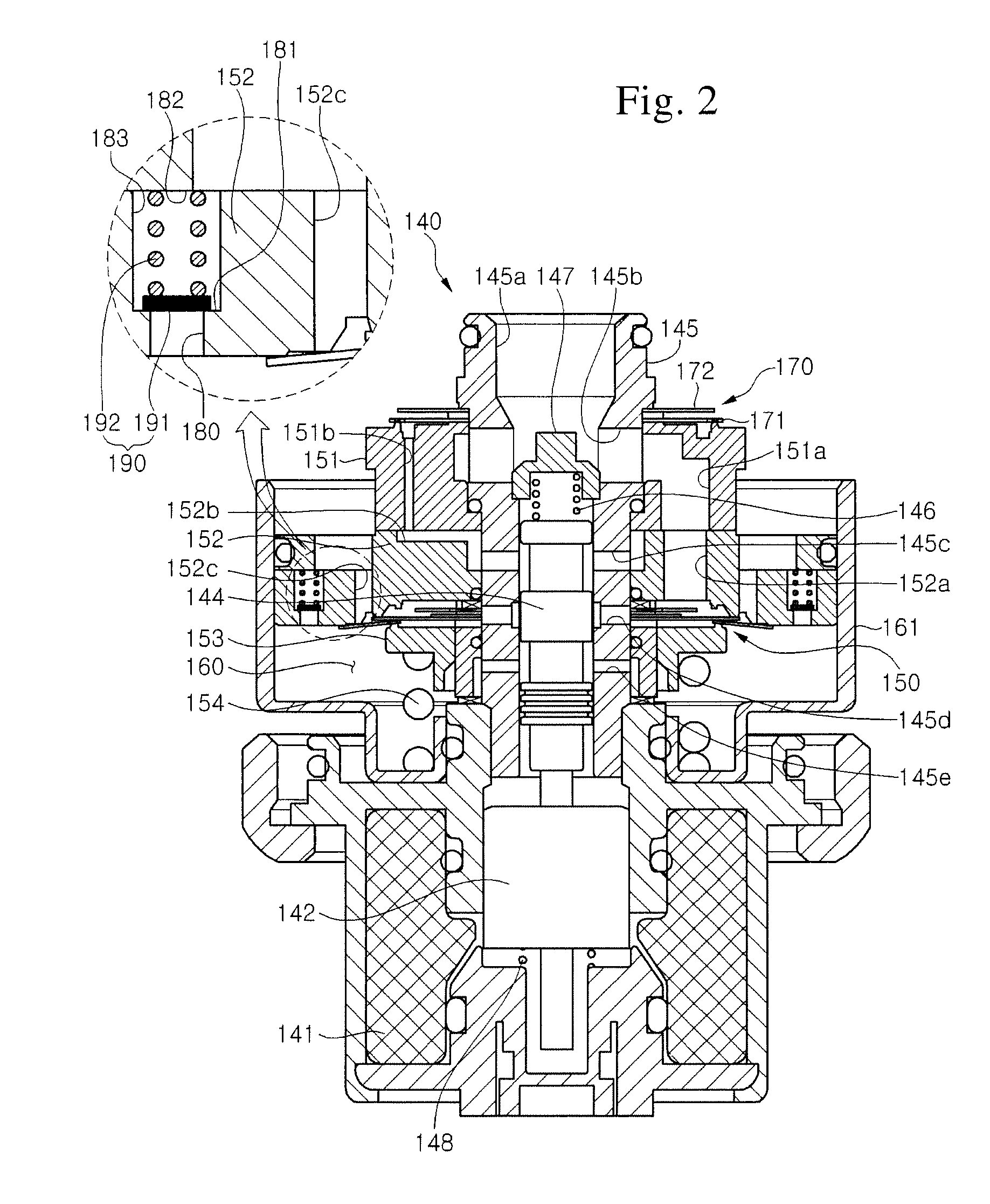
[0048]FIG. 2 is a front cross-sectional view illustrating a damping force variable valve assembly accordi...


PUM


Abstract

A damping force variable valve assembly includes a spool (144) which is moved by a magnetic force, a spool guide (145) which surrounds the spool (144), valve bodies (151, 152), a main valve (150), a back pressure chamber (160) which is formed at the back of the main valve (150), and an elastic opening / closing portion which is installed in the valve body to open and close a pressure adjustment passage (180) communicating the inside of the back pressure chamber (160) with the outside of the back pressure chamber (160). Due to the interaction between the spool (144) and the spool guide (145), the damping force of the shock absorber is variable between a hard mode in which the back pressure of the back pressure chamber (160) is increased and a soft mode in which the back pressure of the back pressure chamber (160) is decreased. In a case where a flow velocity of a working fluid is low in the hard mode, the elastic opening / closing portion opens the pressure adjustment passage (180) when an internal pressure of the back pressure chamber (160) exceeds a preset pressure.

Description

CROSS-REFERENCE(S) TO RELATED APPLICATION[0001]This application claims priority of Korean Patent Application No. 10-2014-0052373, filed on Apr. 30, 2014, in the Korean Intellectual Property Office, which is hereby incorporated by reference in its entirety.BACKGROUND OF THE INVENTION[0002]Field of the Invention[0003]The present invention relates to a damping force variable shock absorber, and more particularly, to a damping force variable valve assembly having a low speed control valve capable of controlling an extremely low speed flow rate and a low speed flow rate when a damping force variable valve operates in a soft mode.[0004]Description of the Related Art[0005]In general, a shock absorber is installed in means of transportation, such as automobile, and improves a ride comfort by absorbing and damping a vibration or shock from a road surface during driving.[0006]The shock absorber includes a piston rod installed in a cylinder to perform compression and rebound strokes, and a pis...

Claims


Application Information

Patent Timeline
Patent Type & Authority Patents(United States)
IPC IPC(8): F16F9/34F16F9/348F16F9/512F16F9/46
CPCF16F9/3415F16F9/34F16F9/3482F16F9/3488F16F9/512F16F9/464F16F2228/066F16F2238/04
Inventor KIM, EUN JOONG
Owner HL MANDO CORP
Why Eureka
Eureka Blog
Learn More