Simultaneous multi-frequency signal processing method

a signal processing and simultaneous multi-frequency technology, applied in the field of signal processing, can solve the problem that waveforms of different frequencies typically require a very large amount of processing power to separate, and achieve the effects of reducing processor requirements for receivers, reducing processing size requirements, and reducing weight and power requirements

Active Publication Date: 2016-11-29
SRC INC
View PDF28 Cites 0 Cited by
  • Summary
  • Abstract
  • Description
  • Claims
  • Application Information

AI Technical Summary

Benefits of technology

[0011]It is therefore an object and advantage of the present invention to provide a method for multi-frequency signal processing.
[0012]It is a further object and advantage of the present invention to provide a method to reduce the processor requirements for receivers capable of simultaneously receiving and digitally processing multiple frequencies simultaneously.
[0013]It is yet another object and advantage of the present invention to provide a system with reduced processing size requirements and similarly reduced weight and power requirements.
[0014]Other objects and advantages of the present invention will in part be obvious, and in part appear hereinafter.
[0015]In accordance with the foregoing objects and advantages, the present invention provides method for a digitally processed receiver that requires a significantly lower processor size than current art. This reduced processor size is achieved by using a special pulse compression or signal filtering technique that samples the received signal at a data rate commensurate with the maximum frequency separation of the separate transmit waveforms, but the pulse compression or filtering calculation is only performed at a rate commensurate with the bandwidth of each individual transmit waveform set. This allows a reduction of the required pulse compression calculations while still allowing for the separation of the return from each individual transmit waveform.BRIEF DESCRIPTION OF THE SEVERAL VIEWS OF THE DRAWING(S)
[0016]The present invention will be more fully understood and appreciated by reading the following

Problems solved by technology

Upon receive, the processing of multiple waveforms of different frequency typically require a very large amount of processing power to separate when received, due to the Nyquist frequency sampling required and the subsequent processing to separate the frequencies.

Method used


Image

  • Simultaneous multi-frequency signal processing method
  • Simultaneous multi-frequency signal processing method
  • Simultaneous multi-frequency signal processing method

Examples


example 1

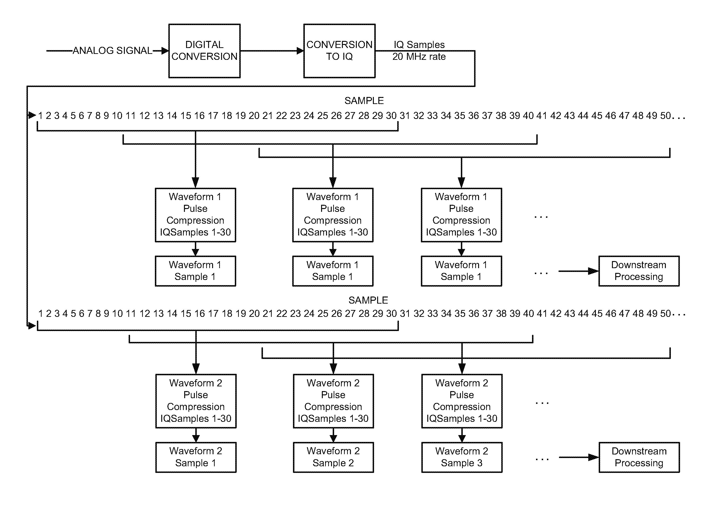
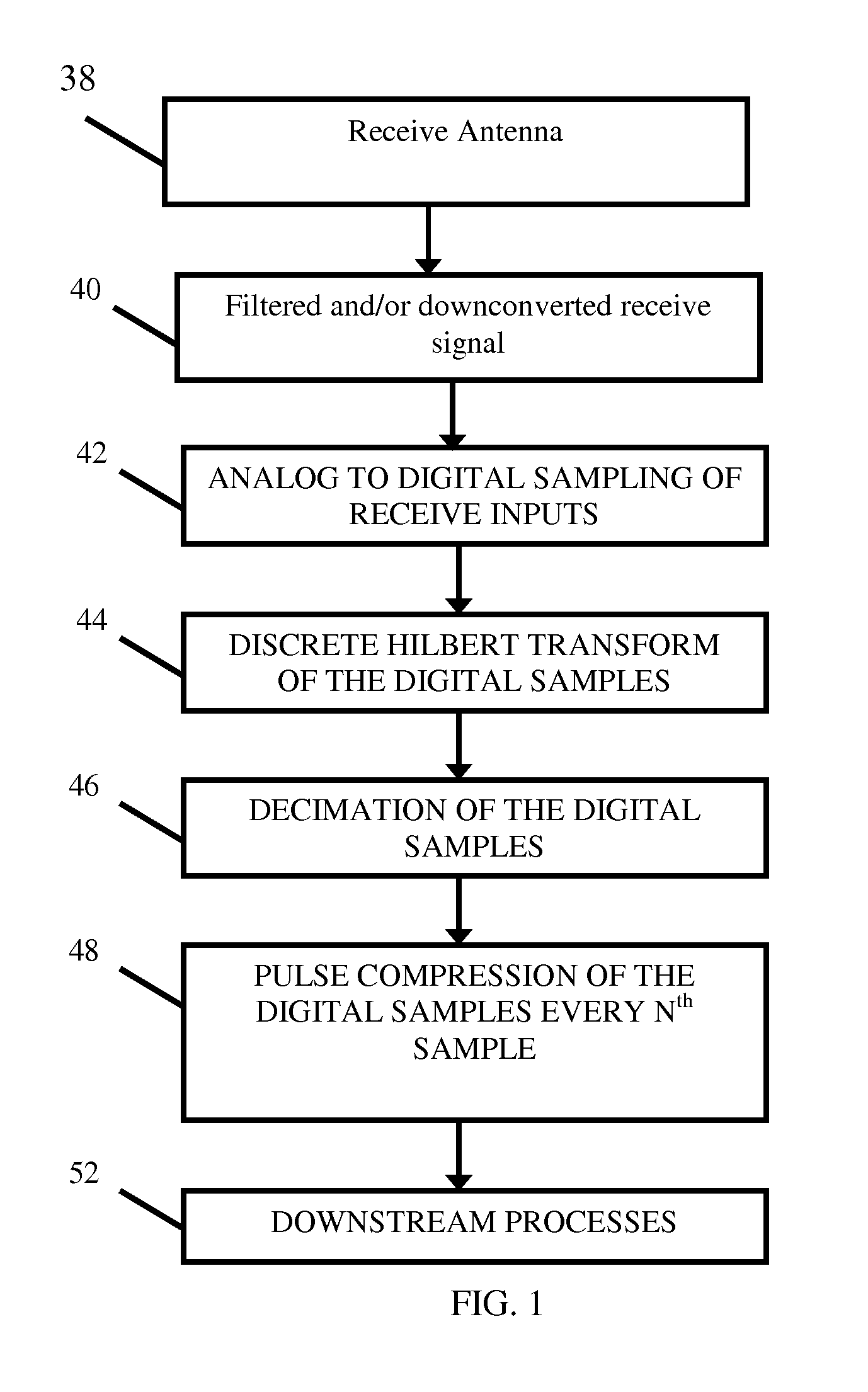
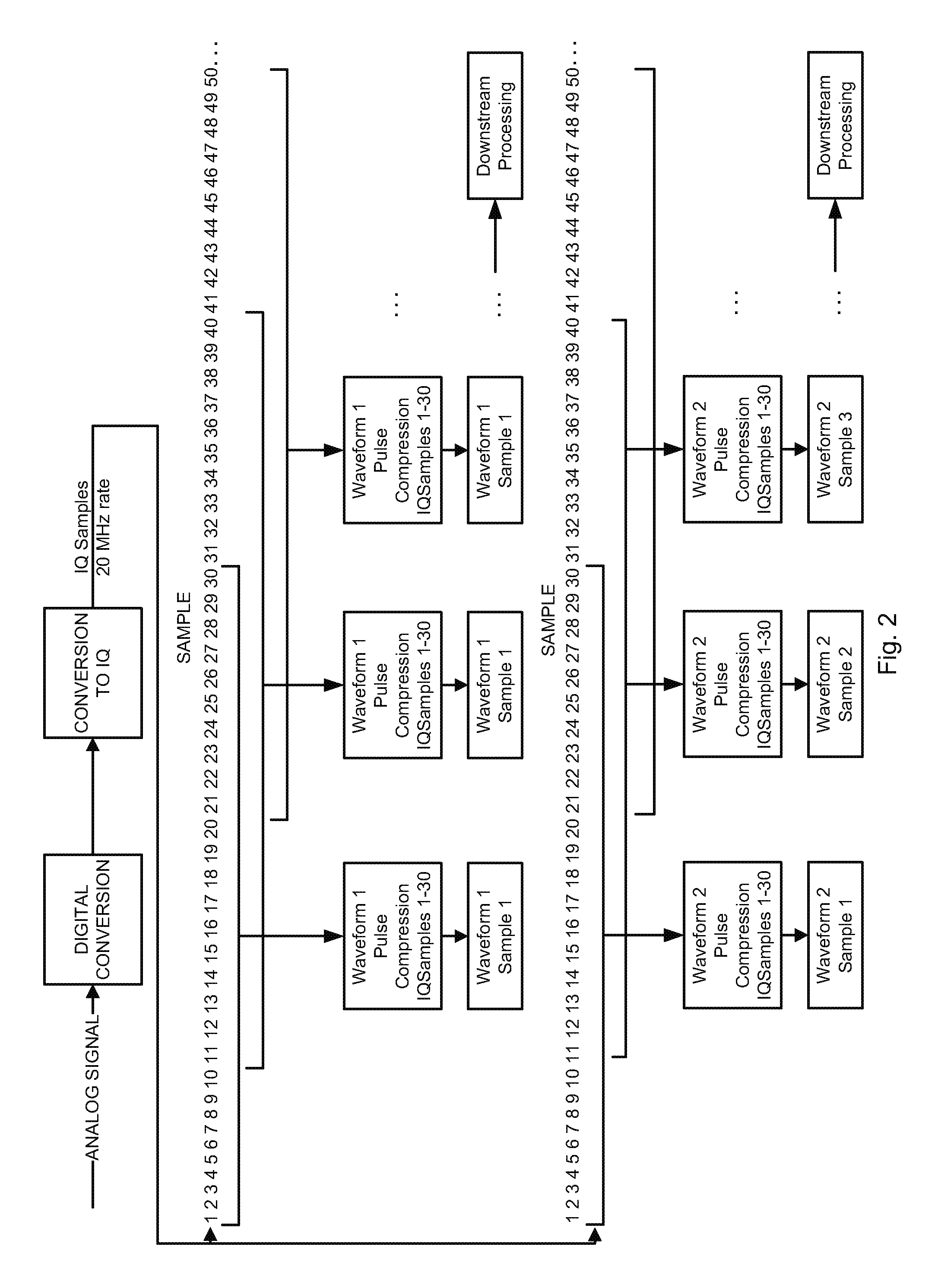
[0026]This Example describes the examination of a set of parameters according to one embodiment of the present invention. Consider a case for which a multi-static radar is required to receive four frequency modulated waveforms of 1.5 microseconds in duration, of 2 MHz bandwidth, with the lowest and highest frequency signal separated by 18 MHz in center frequency (resulting in a peak frequency separation of 20 MHz). The individual waveforms are made separable in the pulse compression, which is executed using a data sampling rate of 20 MHz, and of a width of 30 samples at 20 MHz (corresponding to the pulsewidth). However, each individual transmit bandwidth is 2 MHz, allowing for the correlation to be calculated at every 10th data point. This reduces the total data rate by a factor of 5, but allows for the separation of the return from each individual waveform.


PUM


Abstract

A method for the simultaneous multi-frequency signal processing within a single receiver is presented. The pulse compression or filtering method samples the received signal at a data rate commensurate with the maximum frequency separation of waveforms at separate frequencies being received, but the compression calculations are only performed at a rate commensurate with the bandwidth of each individual transmit waveform set. The method reduces the processor requirements for extracting all available information from these signals.

Description

BACKGROUND OF THE INVENTION[0001]1. Field of Invention[0002]The present invention relates to a method for signal processing, and, more particularly, to a method for the processing of multiple signals of different frequencies which provides a reduction in processing required for the extraction of information from those signals.[0003]2. Description of Prior Art[0004]The digital sampling of signals is well understood throughout industry and academia. The analog to digital sampling rate is typically performed at or above the Nyquist frequency, which refers to the minimum rate at which a signal must be measured in order to extract all available information from the given signal. In general, the Nyquist frequency is a frequency that is equivalent to the frequency of the maximum bandwidth of the signal under analysis. In the case that multiple signals are being simultaneously measured, the Nyquist frequency is equivalent to the difference between the highest and lowest absolute frequency o...

Claims


Application Information

Patent Timeline
Patent Type & Authority Patents(United States)
IPC IPC(8): G01S7/28G01S13/00G01S13/32G01S7/285G01S7/32G01S13/28G01S13/58
CPCG01S13/325G01S7/28G01S7/285G01S7/32G01S13/003G01S13/28G01S13/581
Inventor CULKIN, DANIEL R.
Owner SRC INC
Why Eureka
Try Eureka