
Tire pressure monitoring system and tire pressure transmitter positioning method thereof

A tire pressure monitoring and tire pressure technology, which is applied in tire measurement, tire parts, vehicle parts, etc., can solve the problems of long positioning cycle and complicated calculation method, and achieve the requirements of reduced operating conditions, strong anti-interference ability, and algorithm simple effect

Active Publication Date: 2019-05-28
BAOLONG HUF SHANGHAI ELECTRONICS CO LTD
View PDF5 Cites 0 Cited by
  • Summary
  • Abstract
  • Description
  • Claims
  • Application Information

AI Technical Summary

Problems solved by technology

This method is more reliable, but the calculation method is complex, requiring large-capacity storage on the controller side, and the positioning cycle is longer

Method used


Image

  • Tire pressure monitoring system and tire pressure transmitter positioning method thereof
  • Tire pressure monitoring system and tire pressure transmitter positioning method thereof
  • Tire pressure monitoring system and tire pressure transmitter positioning method thereof

Examples


Embodiment Construction

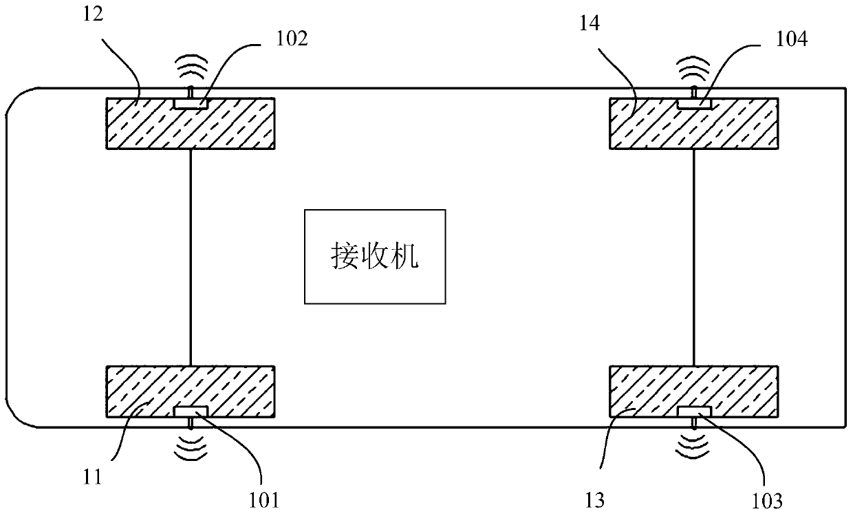
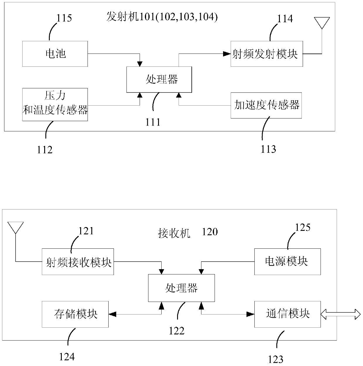
[0030] figure 1 A schematic layout diagram of a tire pressure monitoring system according to an embodiment of the present invention is shown. figure 2 A schematic structural diagram of a tire pressure monitoring system according to an embodiment of the present invention is shown. refer to figure 1 and figure 2 As shown, the tire pressure monitoring system 100 may include a plurality (four are shown) of tire pressure transmitters 101 , 102 , 103 , 104 and a receiver 120 . The tire pressure transmitters 101-104 are respectively arranged on the respective tires 11, 12, 13, 14 of the vehicle. These tires 11, 12, 13, 14 are left front wheel 11, right front wheel 12, left rear wheel 13 and right rear wheel 14, respectively. The purpose of this embodiment is to reliably locate the tire pressure transmitters 101-104 arranged on the respective tires 11-14. This positioning can be regarded as the positioning of the tire pressure transmitters 101-104 as well as the positioning of ...


PUM


Abstract

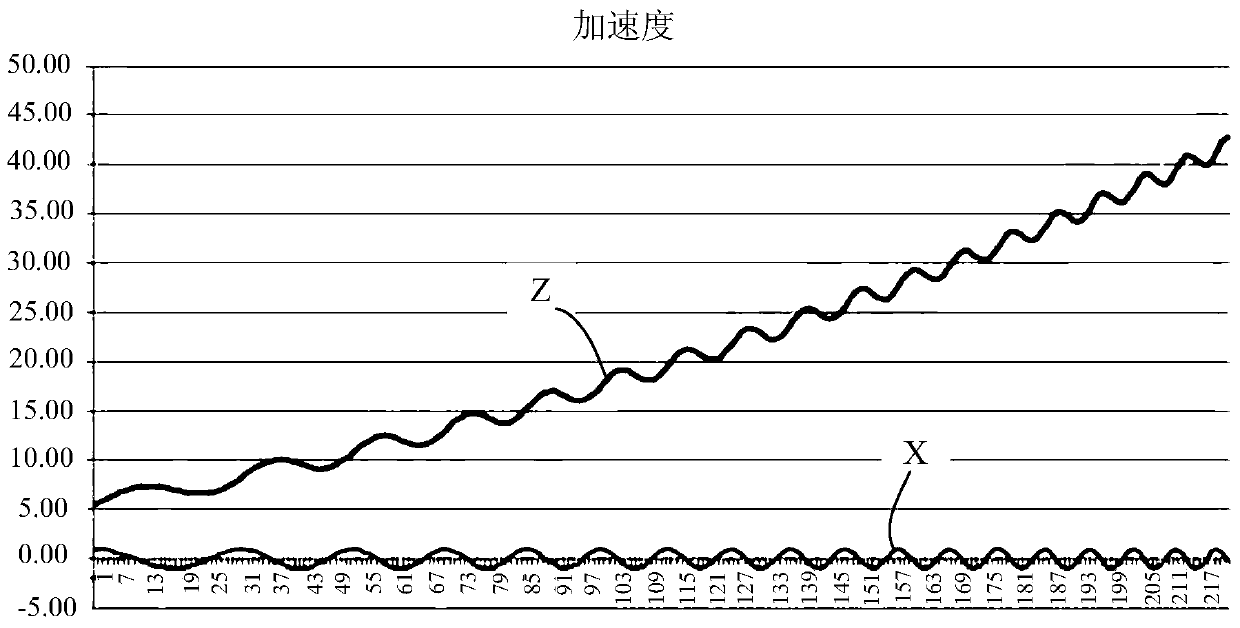
The invention relates to a tire pressure monitoring system capable of locating tire pressure transmitters respectively arranged on each tire of an automobile. The tire pressure monitoring system comprises a plurality of tire pressure transmitters respectively arranged on each tire of an automobile and a receiver machine. Each tire pressure transmitter includes: an acceleration sensor, which is used to collect the acceleration of the corresponding tire and obtain an acceleration signal; a first processor, which generates an acceleration curve according to the acceleration signal and determines the frequency of the acceleration signal; and a radio frequency transmitting module, which sends the acceleration signal Frequency of. The receiver includes: a radio frequency receiving module, which receives the frequency of each acceleration signal sent by each tire pressure transmitter; a communication module, which receives the steering signal of the car; and a second processor, which connects the radio frequency receiving module and the communication module, the first The second processor determines the tire position where each acceleration sensor is located according to the frequency relationship of each acceleration signal during the steering period indicated by the steering signal.

Description

technical field [0001] The invention relates to automotive electronic equipment, in particular to a tire pressure monitoring system and a tire pressure transmitter positioning method thereof. Background technique [0002] Pressure is the most critical parameter of tires, too high or too low tire pressure will increase fuel consumption per kilometer and reduce tire life. The data shows that tire pressure is 25% lower than normal, tire life is reduced by 60%, and fuel consumption increases by 3%. In addition, the size of the tire pressure directly affects the safety of the car. Therefore, it is very necessary to install electronic sensing products on tires for real-time monitoring of tire pressure. Tire Pressure Monitoring System (TPMS) is a kind of automotive electronic equipment proposed for this purpose. [0003] A TPMS system generally includes a tire pressure transmitter installed in each tire of a car and a receiver installed in the body of the car. When a car has ti...

Claims


Application Information

Patent Timeline
IPC IPC(8): B60C23/02
CPCB60C23/0416B60C23/0489
Inventor 史卫华李威傅国锋
Owner BAOLONG HUF SHANGHAI ELECTRONICS CO LTD
Learn More