Shutter device for an electrical switchgear panel, and related switchgear panel

a switchgear panel and switchgear technology, applied in the direction of shutters/guards preventing contact access, switchgear details, electrical apparatus, etc., can solve the problems of complex and cumbersome mechanisms, inability to replace, and inability to meet the requirements of the new circuit breaker

Active Publication Date: 2016-12-06
ABB (SCHWEIZ) AG
View PDF17 Cites 5 Cited by
  • Summary
  • Abstract
  • Description
  • Claims
  • Application Information

AI Technical Summary

Benefits of technology

[0014]A shutter device is disclosed for an electric switchgear panel, the shutter device comprising: a base configured to be placed on a bearing surface inside a switchgear panel, the base being configured to support a current switching device, which is movable between a connected position wherein the switching device is electrically connected to an associated electrical circuit and a disconnected position wherein the switching device is electrically separated from the associated electrical circuit; a frame having at least a portion which rises up transversally from the base and delimits a through aperture; a movable shutter operatively associated with the base and the frame; and an actuating mechanism connected to move the shutter between a first position where the shutter closes at least partially the through aperture to prevent electrical connection of the current switching device with the electrical circuit and a second position wherein the shutter is retracted and leaves the through aperture at least partially opened for allowing electrical connection of the current switching device with the electrical circuit.

Problems solved by technology

For example, the movement of the movable partitioning walls or shutter panels can be actuated through complex and cumbersome mechanisms which most of the times are adapted “ad hoc” for the specific application.
These issues can be important when executing retrofitting or maintenance operations on previously installed switchgears.
Such replacements can be an issue, for example, because the circuit breaker to be replaced is old and no longer produced by the original manufacturer, or because the user wishes to use circuit breakers from different manufacturers.
Accordingly, compatibility issues may arise between the new circuit breaker to be used and the structural and / or functional characteristics of the existing switchgear panel into which the new circuit breaker has to be installed.
For example, the distance between the pre-existing contact pieces of the electric circuit may be totally different and unsuitable with respect to the distance of the corresponding input and output connection contacts of the circuit breaker.
One rather expensive solution is to replace the entire switchgear panel, instead of retrofitting the switchgear panel by replacing only the circuit breaker.
Such a customized approach can use extensive qualified resources and can face practical problems, for example, an ad-hoc solution for each retrofit intervention may need to be designed including knowing the specific dimensions and functionalities of the original circuit breaker and / or related panel.

Method used


Image

  • Shutter device for an electrical switchgear panel, and related switchgear panel
  • Shutter device for an electrical switchgear panel, and related switchgear panel
  • Shutter device for an electrical switchgear panel, and related switchgear panel

Examples


Embodiment Construction

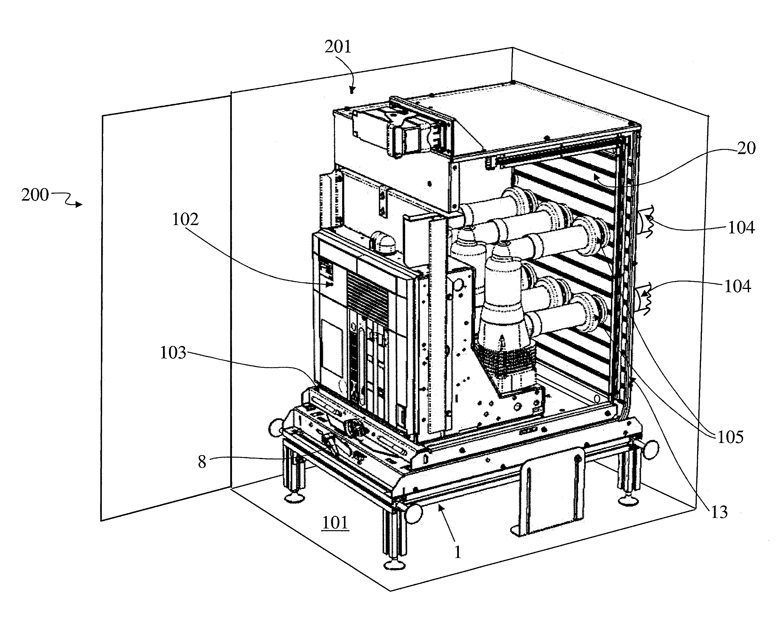
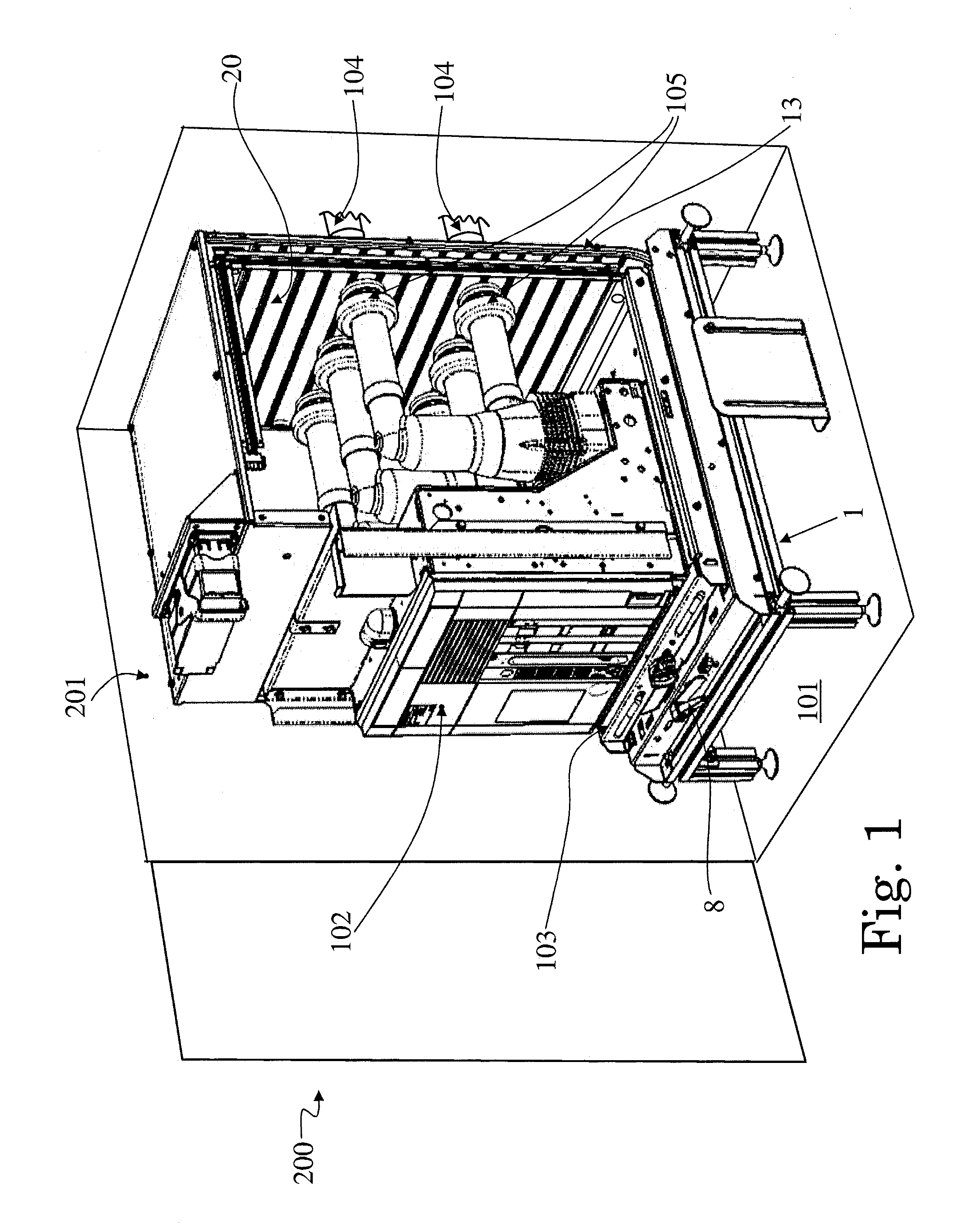
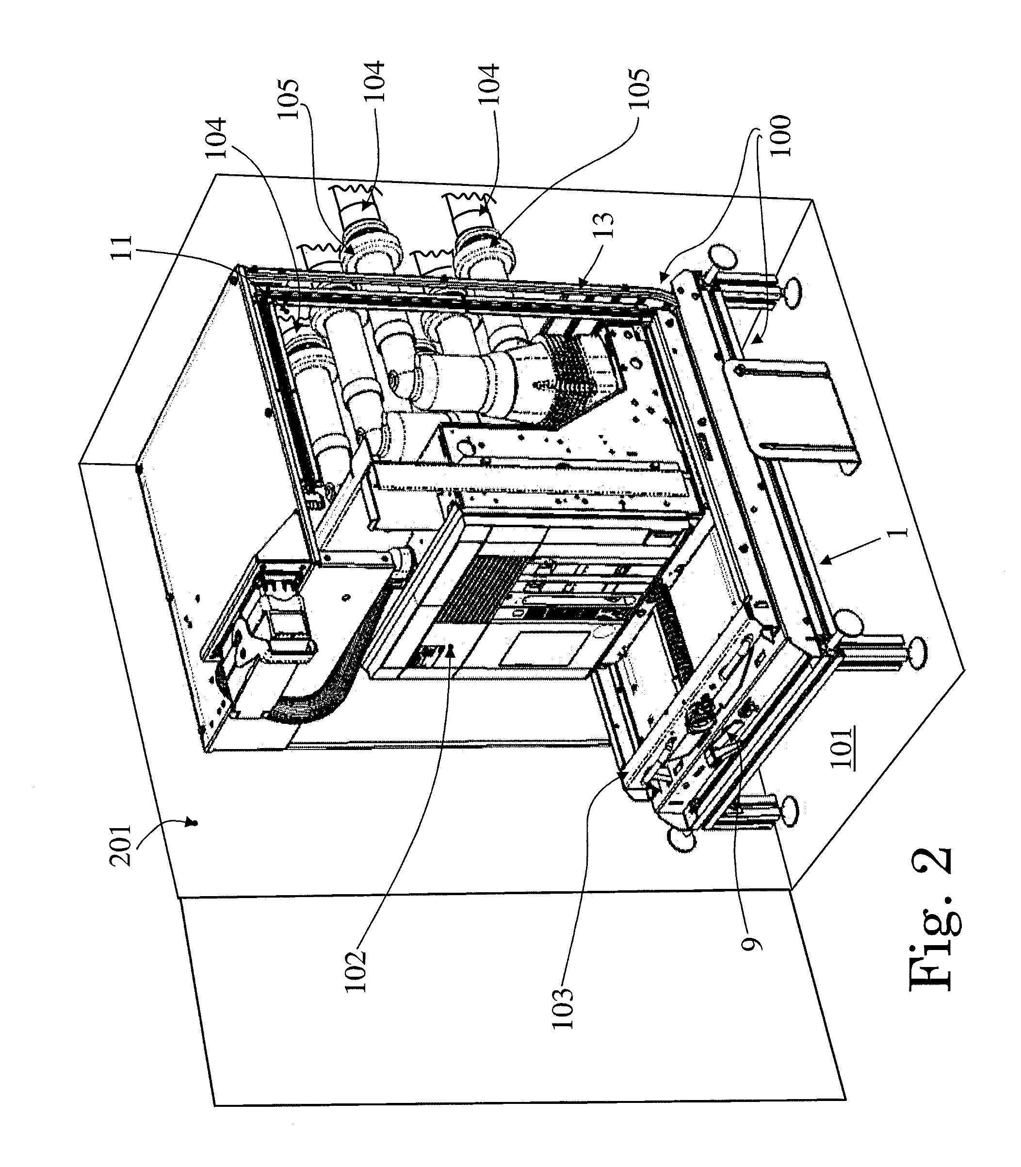
[0026]In accordance with an exemplary, a shutter device is disclosed for an electric switchgear panel, wherein the shutter device can include a base suitable to be placed on a bearing surface inside the switchgear panel, the base being adapted to support, positioned thereon, a current switching device movable between a connected position wherein the switching device is electrically connected to an associated electrical circuit and a disconnected position wherein the switching device is electrically separated from the corresponding electrical circuit, a frame having at least a portion which rises up transversally from the base and delimits a through aperture, a movable shutter operatively associated with the base and the frame and an actuating mechanism adapted to move the shutter between a first position where the shutter closes at least partially the through aperture preventing the electrical connection of the current switching device with the electrical circuit and a second positi...


PUM


Abstract

A shutter device is disclosed for an electric switchgear panel, including a base configured to be placed on a bearing surface inside the switchgear panel, the base being adapted to support, positioned thereon, a current switching device movable between a connected position wherein the switching device is electrically connected to an associated electrical circuit and a disconnected position wherein the switching device is electrically separated from the corresponding electrical circuit, a frame having at least a portion which rises up transversally from the base and delimits a through aperture, a movable shutter operatively associated with the base and the frame and an actuating mechanism adapted to move the shutter between a first position where the shutter closes at least partially the through aperture and a second position wherein the shutter is retracted and leaves the through aperture at least partially opened.

Description

RELATED APPLICATION(S)[0001]This application is a continuation of International Application No. PCT / EP2013 / 059850 filed on May 13, 2013, and claims priority to European Patent Application No. 12171301.0 filed on Jun. 8, 2012, the entire content of both of which is incorporated herein by reference.FIELD[0002]The present disclosure relates to a shutter device for an electrical switchgear panel, and to a switchgear panel using such a shutter device.BACKGROUND INFORMATION[0003]The use of switchgear panels is known in the field of electrical distribution; from a structural point of view, known switchgear panels, which can be also indicated with the equivalent terms of electric switchboards, or switchgear or electric panels, or similar definitions, can include a metallic cubicle that is internally divided into several compartments or cells housing various apparatuses and equipment. For example, one compartment can house a switching unit, such as a circuit breaker, a second compartment can...

Claims


Application Information

Patent Timeline
Patent Type & Authority Patents(United States)
IPC IPC(8): H02B11/24H01H9/22H02B11/28H02B11/02H02B11/133H02B1/14
CPCH02B11/24H01H9/22H02B11/02H02B11/133H02B11/28H02B1/14
Inventor CAPELLI, FABIOCARERA, DAVIDGEMME, CARLOPELLEGRINI, FABIO
Owner ABB (SCHWEIZ) AG
Why Eureka
Try Eureka