Method for determining transmission power

a transmission power and power technology, applied in power management, electrical equipment, radio transmission, etc., can solve the problem that transmission power cannot be thoughtlessly increased

Inactive Publication Date: 2016-12-06
LG ELECTRONICS INC
View PDF4 Cites 0 Cited by
  • Summary
  • Abstract
  • Description
  • Claims
  • Application Information

AI Technical Summary

Benefits of technology

[0015]In the decision step, the transmission power toward the intended receiver may be decided in consideration of a minimization of an outage probability of the unwanted over hearer.

Problems solved by technology

However, when the transmission power is increased, since the transmission power is overheard by a third person, the transmission power may not be thoughtlessly increased.

Method used


Image

  • Method for determining transmission power
  • Method for determining transmission power
  • Method for determining transmission power

Examples


Embodiment Construction

[0025]Reference will now be made in detail to the preferred embodiments of the present invention, examples of which are illustrated in the accompanying drawings. It will also be apparent to those skilled in the art that various modifications and variations can be made in the present invention without departing from the spirit or scope of the invention. Thus, it is intended that the present invention cover modifications and variations of this invention provided they come within the scope of the appended claims and their equivalents.

[0026]Description will now be given in detail of a drain device and a refrigerator having the same according to an embodiment, with reference to the accompanying drawings.

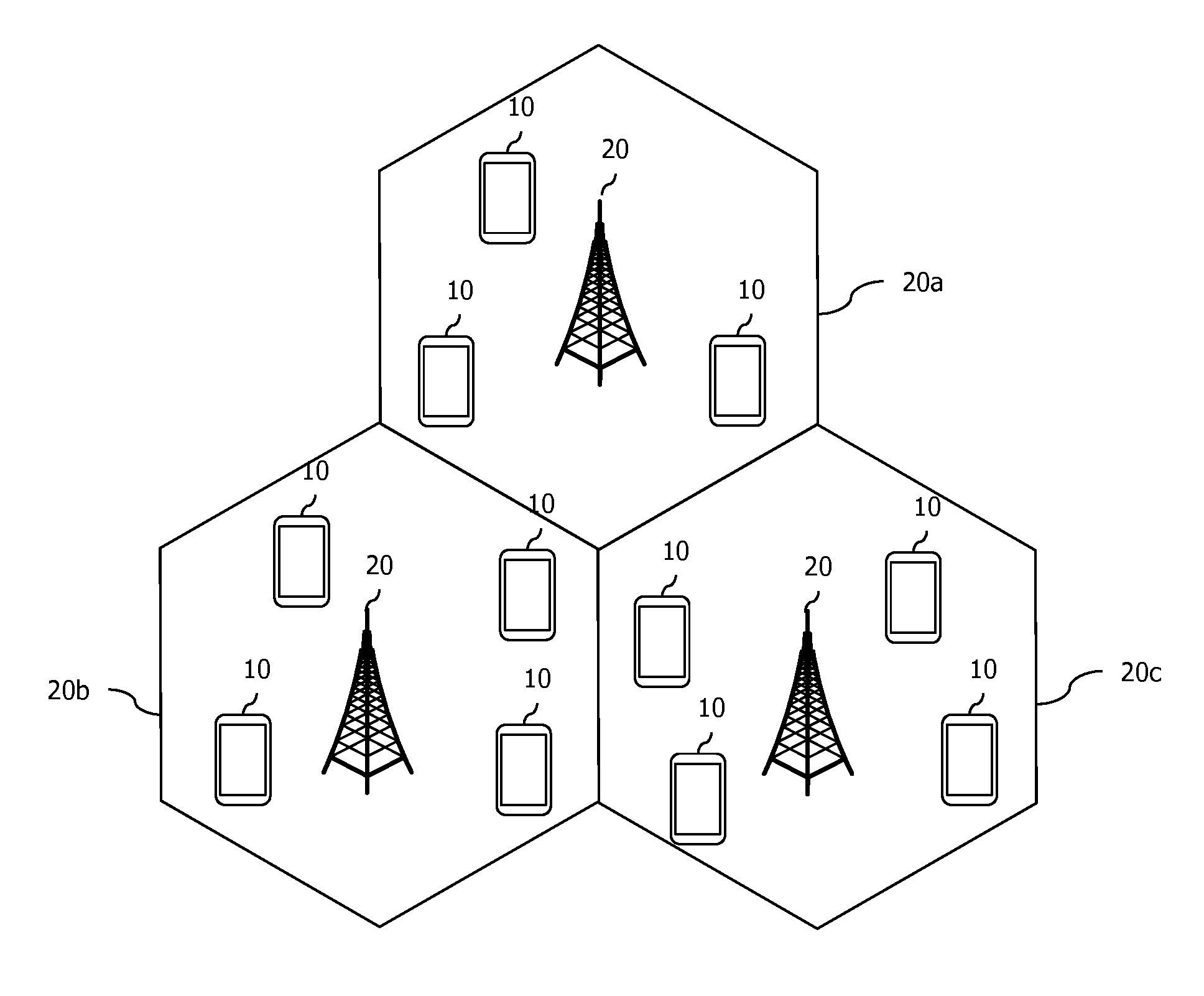
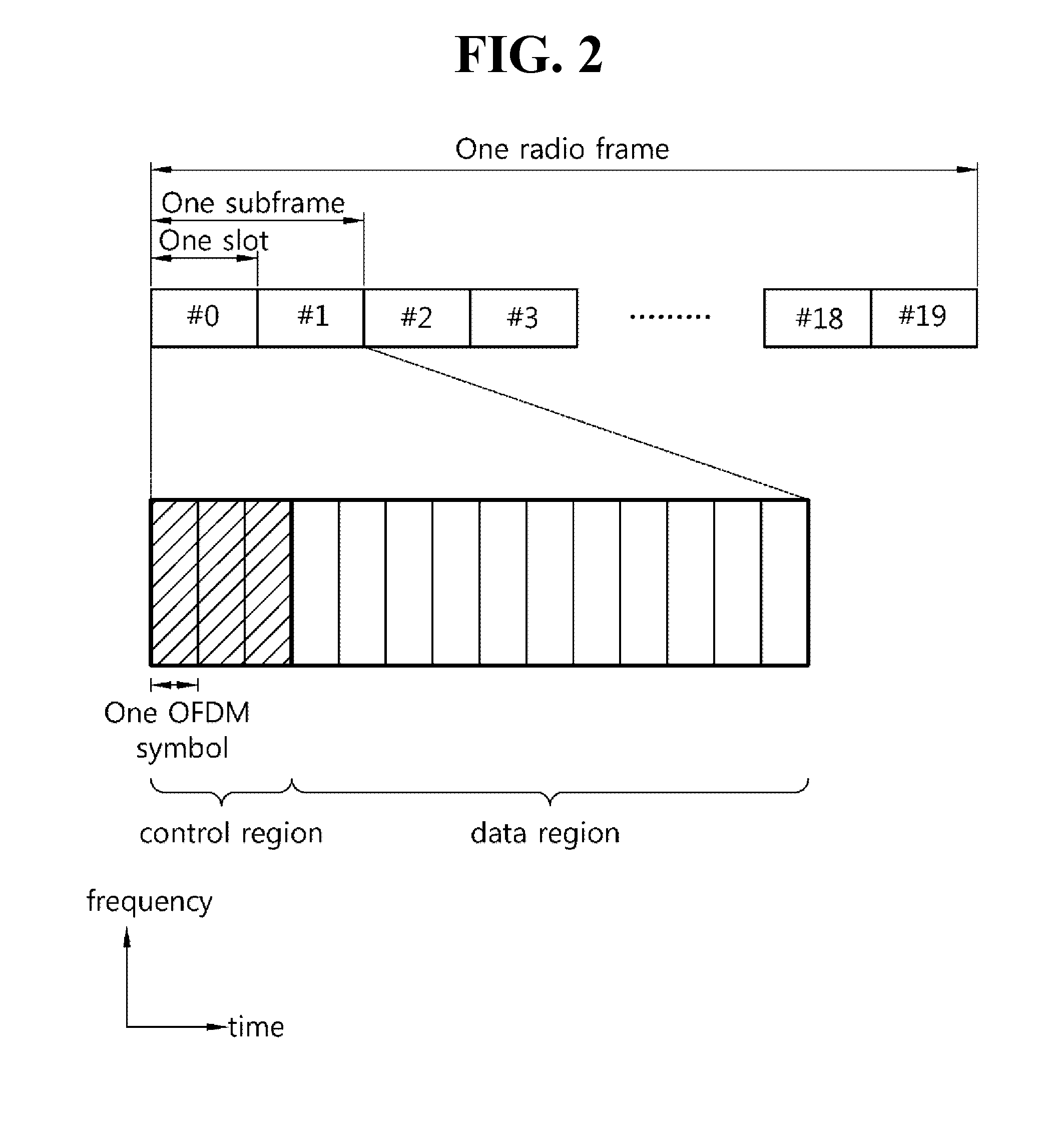
[0027]The present invention will be described on the basis of a universal mobile telecommunication system (UMTS) and an evolved packet core (EPC). However, the present invention is not limited to such communication systems, and it may be also applicable to all kinds of communication syste...


PUM


Abstract

There is a provided a method for deciding transmission power to securely transmit data, the method comprising: determining a transmission rate toward an intended receiver, based on an upper limit of a decoding error probability of the intended receiver and a lower limit of a decoding error probability of an unwanted over hearer; and deciding a transmission power toward the intended receiver based on the upper limit and the lower limit. Here, if the upper limit is lower than the lower limit, the transmission toward the intended receiver is not performed.

Description

CROSS-REFERENCE TO RELATED APPLICATIONS[0001]Pursuant to 35 U.S.C. §119(e), this application claims the benefit of U.S. Provisional Patent Application Ser. No. 61 / 901,434, filed on Nov. 7, 2013, the contents of which are hereby incorporated by reference herein in its entirety.TECHNICAL FIELD[0002]The present invention relates to a method for determining transmission power.BACKGROUND ART[0003]FIG. 1 illustrates a wireless communication system.[0004]As seen with reference to FIG. 1, the wireless communication system includes at least one base station (BS) 20. Each base station 20 provides a communication service to specific geographical areas (generally, referred to as cells) 20a, 20b, and 20c. The cell can be further divided into a plurality of areas (sectors). A terminal (user equipment, UE) 10 may be fixed or movable and may be called other terms such as a mobile station (MS), a mobile terminal (MT), a user terminal (UT), a subscriber station (SS), a wireless device, a personal dig...

Claims


Application Information

Patent Timeline
Patent Type & Authority Patents(United States)
IPC IPC(8): H04B7/00H04W52/26H04W52/20
CPCH04W52/267H04W52/20
Inventor HWANG, DAESUNGKIM, ILMIN
Owner LG ELECTRONICS INC
Why Eureka
Try Eureka