Electronic cigarette

a technology of electronic cigarettes and batteries, which is applied in the field of electric heating products, can solve the problems of complicated process and damage to the batteries of the electronic cigarettes, and achieve the effects of convenient manufacturing, reduced sleeves, and convenient manufacturing

Inactive Publication Date: 2016-12-13
HUIZHOU KIMREE TECH
View PDF9 Cites 43 Cited by
  • Summary
  • Abstract
  • Description
  • Claims
  • Application Information

AI Technical Summary

Benefits of technology

[0007]The object of the present invention is to provide an electronic cigarette, which has an air inlet on a suction nozzle and an airflow channel in the smoking component, to avoid the drawbacks of complicated manufacturing process, inconvenient to use and the batteries may be damaged in the prior art.
[0021]An electronic cigarette of the present invention has following benefit effect: because an air inlet is located at outer edge of the suction nozzle, and an airflow channel is arranged inside a smoking component to communicate with the air inlet and an air outlet, thereby atomized smoke will not pass through the inner of a battery component, which would avoid the battery rod from being damaged. Because the suction nozzle is at least extended into the cavity, therefore the length of the sleeve can be reduced or can be omitted, which is convenient to manufacture. Also the airflow channel is not defined at an area of thread junction or in the battery rod, which is easy to manufacture.

Problems solved by technology

The air inlet defined in the area of thread junction make producing process complicated, while the air inlet defined in the area of a light cap would make the batteries in the battery rod of the electronic cigarette be damaged by the backflow of the hot atomized smoke.

Method used


Image

  • Electronic cigarette
  • Electronic cigarette
  • Electronic cigarette

Examples


embodiment 1

A First Method of Embodiment 1

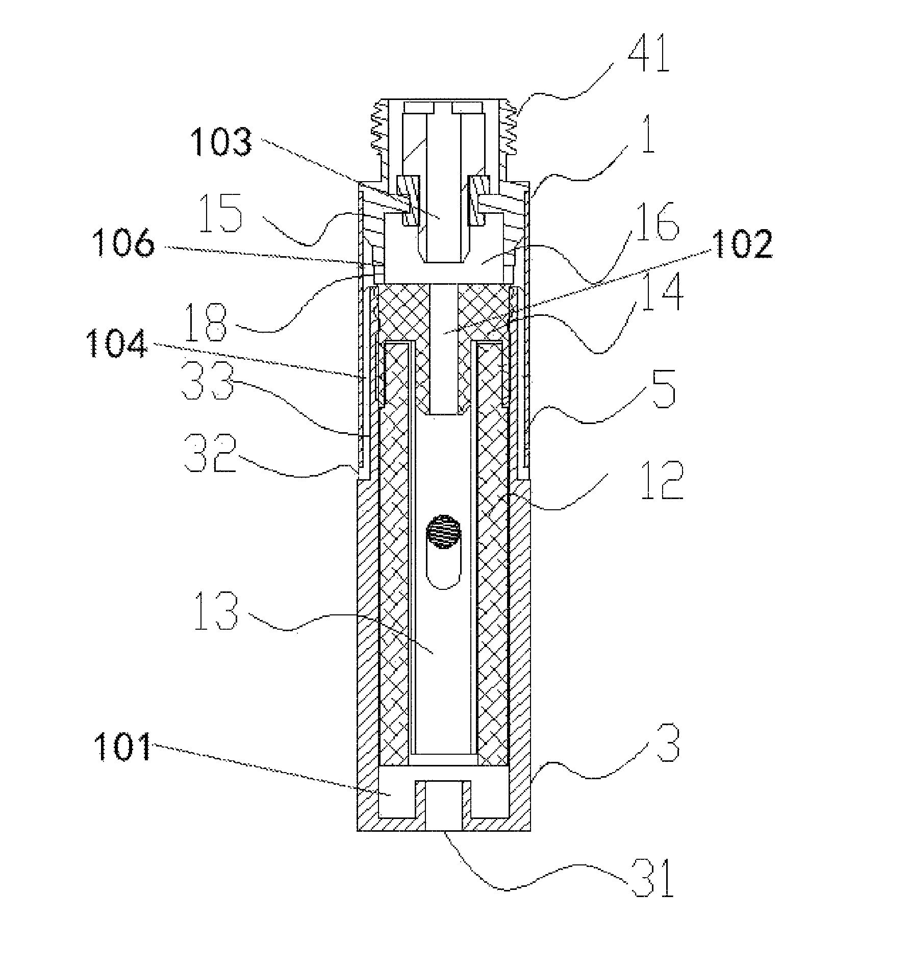
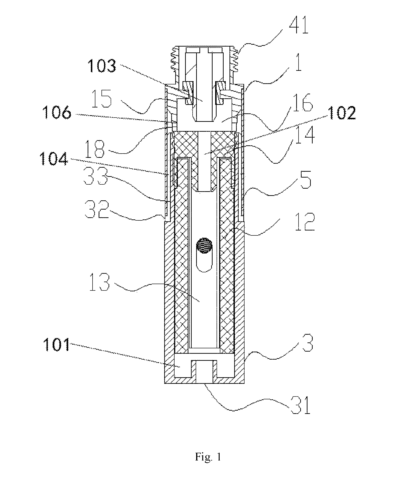
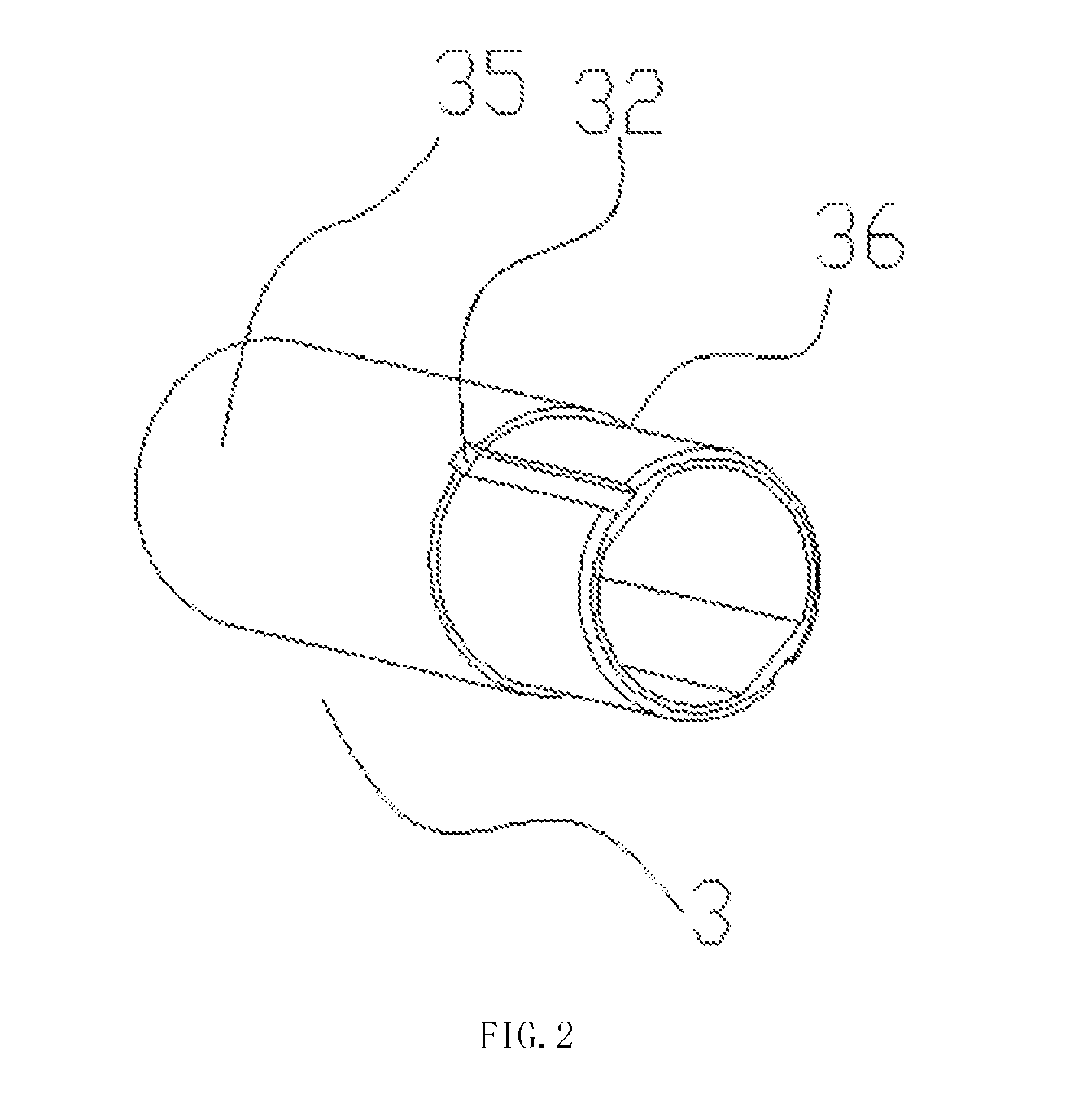
[0034]Referring to FIG. 1 and FIG. 2, the smoking component 1 includes a sleeve 5. The suction nozzle 3 includes a main body 35 and a first connecting portion 36 axially extended toward the battery rod 2. The diameter of the first connecting portion 36 is less than that of the main body 35, and the first connecting portion 36 has a first groove 33. The sleeve 5 is sleeved on the first connecting portion 36, and a channel surrounded by the sleeve 5 and the first groove 33 is defined as a first passage 104. The first passage 104 communicates with the cavity 16 and the air inlet 32 to cooperatively form the second airflow channel 103.

[0035]A second method of embodiment 1:

[0036]The smoking component 1 includes a sleeve 5. The suction nozzle 3 includes a main body 35 and a first connecting portion 36 axially extended toward the battery rod 2. The diameter of the first connecting portion 36 is less than that of the main body 35. The inner wall of the sleeve 5...

embodiment 2

[0042]Referring to FIG. 3 and FIG. 4, the air inlet 32 is a through hole, which is radially through the suction nozzle 3 into the cavity 16, and the second airflow channel 103 is formed by the air inlet 32 and the cavity 16 communicating with each other. The suction nozzle 3 axially extends to or beyond the cavity 16.

[0043]In the illustrated embodiment 2, a sleeve is not needed, the suction nozzle 13 axially extends to or beyond the cavity 16 to play the role of the sleeve 5 in the first embodiment, and the atomized cavity 13 and the atomizer base 14 are both located inside the suction nozzle 3. The air outlets 31 can be axially or radially defined on an end of the suction nozzle 3, and the end is far away from the battery rod 2.

[0044]In the first embodiment, there can be one or more second passages 105. In both the first and second embodiment, there can be one or more air inlets 32. Usually, for the uniformity of the atomized smoke, two second passages 105 and two air inlets 32 are...


PUM


Abstract

The present invention relates to an electronic cigarette, which includes a smoking component having a suction nozzle and a battery rod. The suction nozzle is configured at an end of the smoking component and is far away from the battery rod. The smoking component further comprises a receiving chamber having an atomizer base which separates the receiving chamber into an atomized cavity and a cavity. One end of the suction nozzle, being far away from the battery rod, has an air outlet, and another end of the suction nozzle, being close to the cavity, has an air inlet. The smoking component has airflow through channel connecting the air outlet, the cavity and the air inlet. The electronic cigarette of the present invention is easy to be manufactured, and the batteries in the battery rod of the electronic cigarette can be protected from be damaged by the hot smoking airflow.

Description

CROSS-REFERENCE TO RELATED APPLICATIONS[0001]This application is a continuation of International Patent Application No. PCT / CN2013 / 074163, with an international filing date of Apr. 12, 2013, designating the United States, now pending. The contents of these specifications are incorporated herein by reference.BACKGROUND[0002]1. Technical Field[0003]The present invention relates to electric heating products, and more particularly to an electronic cigarette.[0004]2. Description of Related Art[0005]At present, an air inlet of an electronic cigarette is usually defined in an area of thread junction between an atomizer and a battery rod or in an area of a light cap. The air inlet defined in the area of thread junction make producing process complicated, while the air inlet defined in the area of a light cap would make the batteries in the battery rod of the electronic cigarette be damaged by the backflow of the hot atomized smoke.[0006]Therefore, there is room for improvement within the ar...

Claims


Application Information

Patent Timeline
Patent Type & Authority Patents(United States)
IPC IPC(8): A24F47/00A24F40/485
CPCA24F47/008A24F40/485
Inventor LIU, QIUMING
Owner HUIZHOU KIMREE TECH
Why Eureka
Try Eureka