Communication structure with connecting assembly

a communication structure and assembly technology, applied in the direction of supporting structure mounting, coupling device connection, electrical apparatus, etc., can solve the problems of increasing the manufacturing cost of the communication system, and losing data transmission signals between the i/o modules, so as to facilitate the expansion of more communication nodes

Active Publication Date: 2016-12-27
VIEWMOVE TECH
View PDF21 Cites 1 Cited by
  • Summary
  • Abstract
  • Description
  • Claims
  • Application Information

AI Technical Summary

Benefits of technology

[0006]One objective of the present invention is to provide a communication structure with a connecting assembly so that the communication structure stably and electrically connected to another communication structure by using the connecting assembly and at least two communication structures are electrically connected together to construct a communication system for conveniently expanding more communication nodes.

Problems solved by technology

However, the contact statuses between the elastic contacts of the I / O modules cannot exactly and stably form electrical connections so that the data transmission signals between the I / O modules will be lost.
Furthermore, when more and more I / O modules in a module group are used to construct the communication system to expand the operation nodes of the communication system, redundant nodes in the expanded I / O module will not be used, which increases manufacturing cost.
If there is a need to expand the communication system from thirty-two I / O modules to thirty-three I / O modules, it is required to add an additional module group with the sixteen I / O modules to the original two module groups to form three module groups with forty-eight I / O modules, which generates fifteen redundant I / O modules to increase the manufacturing cost of the communication system.

Method used


Image

  • Communication structure with connecting assembly
  • Communication structure with connecting assembly
  • Communication structure with connecting assembly

Examples


Embodiment Construction

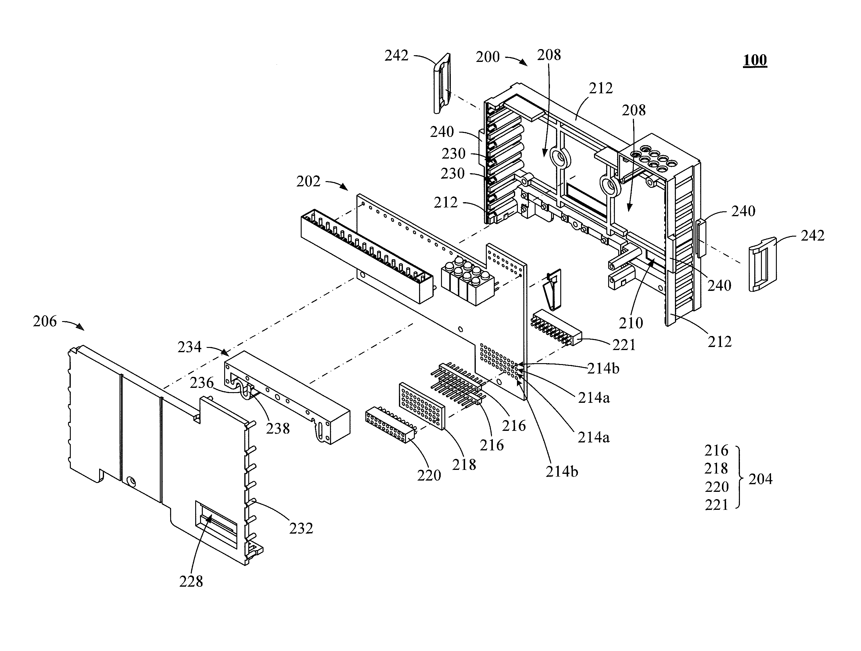
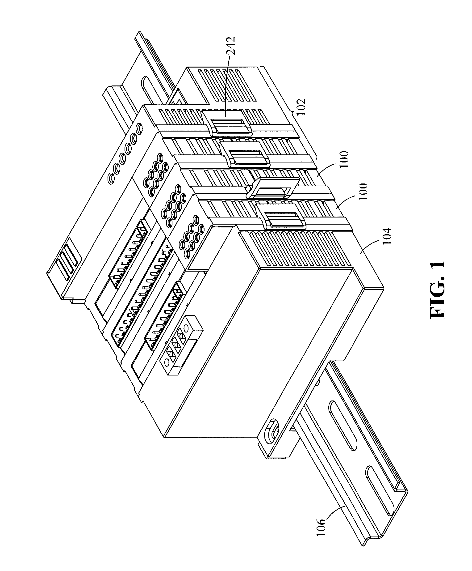
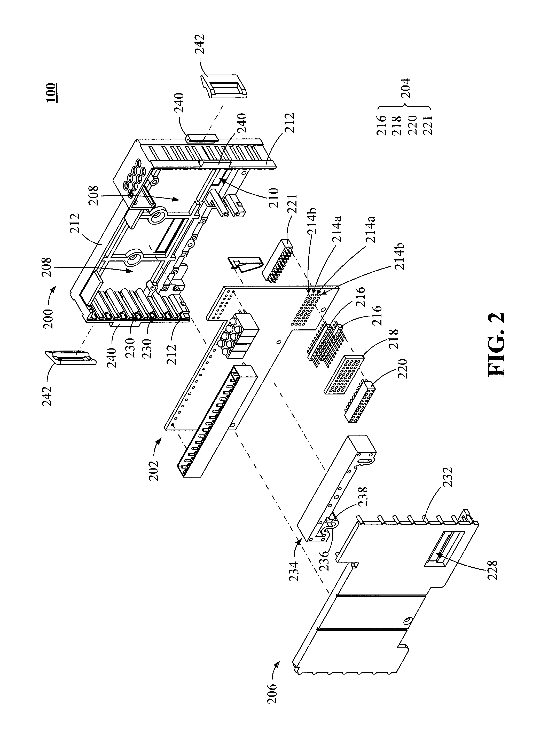
[0021]Referring to FIG. 1, which is a schematic three-dimensional view of a communication system with a connecting assembly 204 according to one embodiment of the present invention. The communication system comprises at least one communication structure 100, a coupling device 102 and a terminal device 104. The at least one communication structure 100 is connected to the coupling device 102 to the terminal device 104 wherein the at least one communication structure 100 is disposed between the coupling device 102 and the terminal device 104. The at least one communication structure 100, e.g. two communication structures 100, a coupling device 102 and a terminal device 104 are fastened to a rail unit 106. The coupling device 102 is used to transmit a first instruction packet string, e.g. an instruction packet serial, to the at least one communication structure 100 wherein the first instruction packet string comprises a plurality of instruction packets. The at least one communication st...


PUM


Abstract

A communication structure with connecting assembly is described. The communication structure comprises a housing base, a circuit board, a connecting assembly and a cover body wherein the connecting assembly comprises a plurality of conducting terminals, an adapting board coupled to the conducting terminals, and a first connecting socket coupled to the adapting board. The communication structure stably and electrically connected to another communication structure by the connecting assembly and at least two communication structures are electrically connected together to construct a communication system for conveniently expending more communication nodes.

Description

BACKGROUND OF THE INVENTION[0001]Field of Invention[0002]The present invention relates to a communication structure, and more particularly to a communication structure with a connecting assembly.[0003]Description of Prior Art[0004]Conventionally, due to the increased demand for product manufacturing process, an automation technology is widely used in a production process and the automation technology usually employs a plurality of serially connected input / output (I / O) modules to transmit a packet serial having data packets wherein a master / slave structure is used to transmit and process the packet serial with the data packets, which are forwarded to the I / O modules, by a serial bus interface protocol. Specifically, when a plurality of I / O modules are serially connected to form a communication system, the I / O modules are electrically connected by elastic contacts each other. However, the contact statuses between the elastic contacts of the I / O modules cannot exactly and stably form e...

Claims


Application Information

Patent Timeline
Patent Type & Authority Patents(United States)
IPC IPC(8): H01R12/71H01R13/506H01R13/514
CPCH01R12/712H01R13/506H01R13/514H01R9/2675H05K7/1468H05K7/1478
Inventor JIANG, SHYH-BIAULIU, LI-YEHLEE, DONG-LIANGHUANG, CHUAN-FUHSIAO, YUN-SHENG
Owner VIEWMOVE TECH
Why Eureka
Try Eureka