Methods and devices for retrofitting footwear to include a reel based closure system

a technology of closure system and reel, applied in the field of closure or tightening system, devices, and methods related to footwear, can solve the problems of footwear not readily recognizable and the coupling of the tensioning mechanism

Active Publication Date: 2017-01-03
BOA TECHNOLOGY
View PDF617 Cites 14 Cited by
  • Summary
  • Abstract
  • Description
  • Claims
  • Application Information

AI Technical Summary

Benefits of technology

[0006]The embodiments described herein provide closure or tightening systems and devices that may be attached to existing footwear without significantly damaging or altering the footwear or otherwise forming significantly visible or other evidence of the attachment. The embodiments also provide methods of attaching closure or tightening systems or devices to existing footwear without significantly damaging or altering the footwear. According to one embodiment, a lacing system that is removably coupleabe with footwear is provided. The lacing system includes a first guide member that is positionable on a first side of the footwear and a second guide member that is positionable on a second side of the footwear opposite the first side. The lacing system also includes a tension member that is guided by the first guide member and the second guide member along a path about the footwear—commonly along a tongue portion of the footwear. The tension member is tensionable to tighten the footwear about a foot by pulling or urging the first and second sides together.
[0008]In some embodiments, the tensioning mechanism is coupled with an elongate panel member that is positionable along a tongue of the footwear. In such embodiments, the tensioning mechanism may be coupled with a distal end of the elongate panel member and a proximal end of the elongate panel member may include a support member that extends roughly orthogonally therefrom. The support member may be coupleable with opposing sides of the footwear's tongue (i.e., the first and second sides of the footwear) to stabilize the elongate panel member. In some embodiments, the support member may be moveable proximally and distally relative to the proximal end of the elongate panel member to accommodate footwear of various shapes and sizes. The proximal end of the elongate panel member may be trimmable and / or opposing ends of the support member may be trimmable to facilitate in positioning of the elongate panel member along the footwear's tongue and / or in coupling of the support member with the opposing sides of the footwear's tongue.
[0016]In some embodiments, the tensioning mechanism is coupled with an elongate panel member. In such embodiments, the method also includes positioning the elongate panel member along a tongue portion of the footwear. In such embodiments, the method may further include coupling a support member of the elongate panel member with opposing sides of the footwear's tongue portion to stabilize the elongate panel member, the support member being coupled toward an end of the elongate panel member opposite the tensioning member. In such embodiments, the method may additionally include adjusting the support member proximally or distally about the elongate panel member to accommodate a shape and / or size of the footwear. In such embodiments, the method may additionally include trimming the end of the elongate panel member to facilitate in positioning of the elongate panel member along the footwear's tongue and / or trimming opposing ends of the support member to facilitate in coupling of the support member with the opposing sides of the footwear's tongue.
[0021]In some embodiments, the tension member is fixedly coupled with the tensioning mechanism prior to coupling the tensioning mechanism with the article and the one or more guide members are slidingly coupled with the tension member. In such embodiments, the method also includes coupling the one or more guide members with the article. In such embodiments, coupling the one or more guide members with the article may removably couple the one or more guide members, tension member, and tensioning mechanism with the article. In such embodiments, coupling the one or more guide members with the article may include inserting a proximal end of the one or more guide members through a respective eyelet of the article.

Problems solved by technology

The lacing system further includes a tensioning mechanism that is coupleable with the footwear and removable therefrom without damaging the footwear so that upon removal of the tensioning mechanism, the coupling of the tensioning mechanism and the footwear is not readily recognizable.

Method used


Image

  • Methods and devices for retrofitting footwear to include a reel based closure system
  • Methods and devices for retrofitting footwear to include a reel based closure system
  • Methods and devices for retrofitting footwear to include a reel based closure system

Examples


embodiment 720

[0091]FIGS. 7E-F illustrate another embodiment 720 of attaching guides to shoes. Specifically, a guide 722a may include a threaded aperture (not shown) within which a threaded post 724a is inserted. The threaded post 724a may be inserted through an eyelet 726 of the shoe and then threaded into the aperture of guide 722a to couple the guide with the shoe. In an alternative embodiment, the guide 722b may include a threaded post that is threaded into an aperture of a bolt or plug 724b. In some embodiments, threading the post or plug 724b with the guide 722b may require a fastening tool, such as a screwdriver, wrench, and the like, or may be performed by hand. In some embodiments, guide 724b may be self-tapping or of the drivable rivet type.

embodiment 730

[0092]FIGS. 7G-J illustrate another embodiment 730 of attaching a guide to a shoe. Specifically, in this embodiment the guide 732 includes a coupling member 734 that is rotationally attached to a main body of guide 732. The coupling member 734 is configured to be inserted within an eyelet 736 of the shoe and rotated relative to guide 732 so that the distal end of the coupling member 734 is positioned adjacent a distal end of the guide 732. The coupling member 734 may be positioned relatively centrally within a main body of guide 732 so that as the coupling member 734 is rotated towards the guide 732, the distal end of the coupling member 734 snaps or locks into place relative to the distal end of guide 732. The guide 732 is locked into place about the shoe as the coupling member 734 locks or snaps into place relative to guide 732.

[0093]The distal ends of the coupling member 734 and guide 732 may include a lumen that is configured to align coaxially as the distal ends of the coupling...

first embodiment

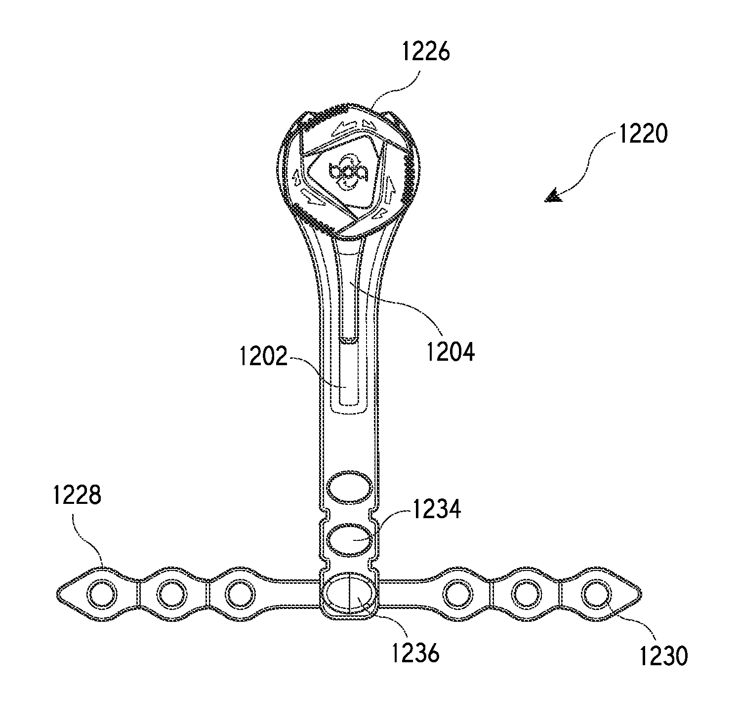
[0124]FIGS. 11A-D illustrate another embodiment in which a shoe may be retrofit to include the reel assembly. In a first embodiment, a panel 1102, which is typically made of a fabric or plastic material, may include a plurality of cuts 1106 that create one or more flaps 1108 that may be used to couple the reel assembly to the panel 1102. For example, a flange 1104 of the reel assembly may be inserted under one or more of the flaps 1108 created in the panel 1102. In one embodiment, opposite edges of the flange 1104 may be inserted under opposing flaps 1108 to couple the reel assembly with the panel 1102. In one embodiment, the flange 1104 may be stitched to the panels 1108 to permanently affix the reel assembly thereto. In another embodiment, the panels 1108 may be adhesively bonded or mechanically fastened to the flange 1104.

[0125]In another embodiment, a panel 1110 may include an aperture 1112 that is sized larger than a top portion of the reel assembly 1116, but sized smaller than...


PUM

PropertyMeasurementUnit
longitudinal lengthaaaaaaaaaa
widthaaaaaaaaaa

Abstract

According to one embodiment, a removable tightening device is described. The tensioning mechanism is removably coupleable with an article without damaging the article so that upon removal, the coupling of the tensioning mechanism with the article is unrecognizable or not readily detectable. The tensioning mechanism is operable with a tension member to maintain a tension of the tension member and thereby maintain a tightness of the article. The tension member is guided along a path about the article, via one or more guide members, and is tensionable, via the tensioning mechanism, to tighten the article.

Description

CROSS-REFERENCES TO RELATED APPLICATIONS[0001]This application claims priority to Provisional U.S. Patent Application No. 61 / 807,251 filed Apr. 1, 2013, entitled “Methods and Devices for Retrofitting Footwear to Include a Reel Based Closure System,” the entire disclosure of which is hereby incorporated by reference, for all purposes, as if fully set forth herein.BACKGROUND[0002]The embodiments described herein are generally related to closure or tightening systems, devices, and methods related to footwear. The embodiments are specifically related to closure or tightening systems and devices that may be retrofit to existing footwear, and methods of retrofitting existing footwear with a closure or tightening system or device.[0003]Footwear commonly includes a closure or tightening system or device. For example, footwear commonly includes shoelace that is threaded through eyelets of the shoe and tensioned to tighten the shoe about the foot. Shoelace may be inconvenient for a user since...

Claims


Application Information

Patent Timeline
Patent Type & Authority Patents(United States)
IPC IPC(8): A43C11/20A43B19/00A43C5/00A43C11/16A43C1/04A43C3/02A43C3/00
CPCA43C11/20A43B19/005A43C1/04A43C3/00A43C3/02A43C5/00A43C11/165Y10T24/3739Y10T29/49826A43C15/00A43C15/061A43C7/00
Inventor LOVETT, KRISTOPHER C.CONVERSE, CHRISTOPHER H.MORGAN, CLARKNICKEL, MICHAEL J.
Owner BOA TECHNOLOGY
Why Eureka
Try Eureka