Indexing welding device for tube

a welding device and tube technology, applied in the field of packaging tubes, can solve the problems of incompressible working time, adverse effect on the intrinsic properties of packaging, and restricted working tim

Active Publication Date: 2017-01-10
AISAPACK HLDG SA
View PDF11 Cites 19 Cited by
  • Summary
  • Abstract
  • Description
  • Claims
  • Application Information

AI Technical Summary

Benefits of technology

[0046]The invention relates to an indexing assembly device for packaging tubes. This device makes it possible to carry out the following successive operations required for the manufacture of a packaging tube:
[0056]In this invention the inertia of the device is lower than in similar devices in the state of the art. As a result indexing time can be reduced, and this offers the possibility of increasing the production rate.
[0057]Stated in other words, the invention makes it possible to increase production rate without reducing welding times.
[0066]The invention makes it possible to increase the number of mandrels in parallel per station without increasing the radial dimensions.
[0067]In accordance with one embodiment of the invention said axis is located in a vertical direction, that is to say in a direction substantially parallel to the direction of the force of gravity. This embodiment is advantageous for a device which is placed on a table. It makes it possible to have all the stations at the same height.

Problems solved by technology

Reduction in working time is restricted by the time of the unit operations on which the quality of the manufactured packaging depends.
Beyond a certain limit this working time becomes incompressible, because reducing it would have an adverse effect on the intrinsic properties of the packaging.
Optimizing indexing time in this type of device is limited by the inertia of the turntable, the diameter of which increases rapidly with the number of mandrels in parallel.
This leads to the disadvantage that each workstation is provided with a specific device for making the approach movement.
As in patent application WO 2004 / 026567 A1 the device disclosed by Kieras has the disadvantage that each workstation requires a specific device for making the approach movement.
This mandrel construction results in increasing the virtual diameter 8 of the circle formed by the ends of the mandrels and therefore results in significant inertia of the device when rotating (moment of inertia).
The device in application WO 2007 / 141711 makes it possible to place all the mandrels in radial movement as a result of a single action, but has the disadvantage of having a large moment of inertia, which during the stages in which turntable 3 is accelerated and decelerated gives rise to significant changes in torque on the axis of the turntable and in production rates.

Method used


Image

  • Indexing welding device for tube
  • Indexing welding device for tube
  • Indexing welding device for tube

Examples


Embodiment Construction

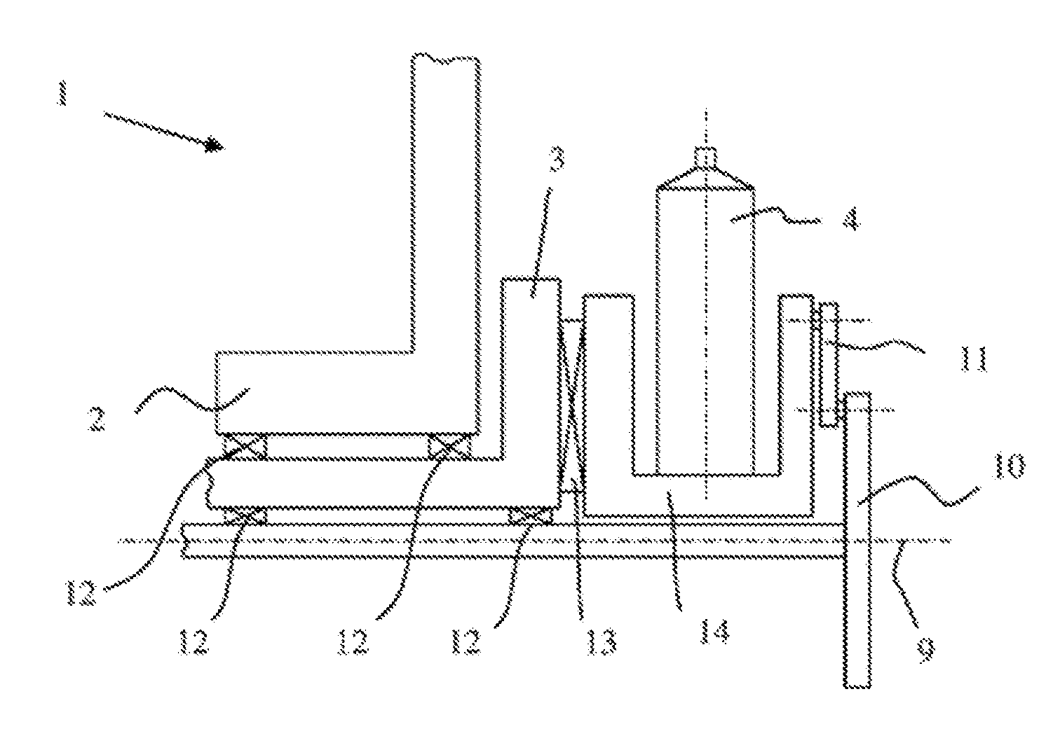
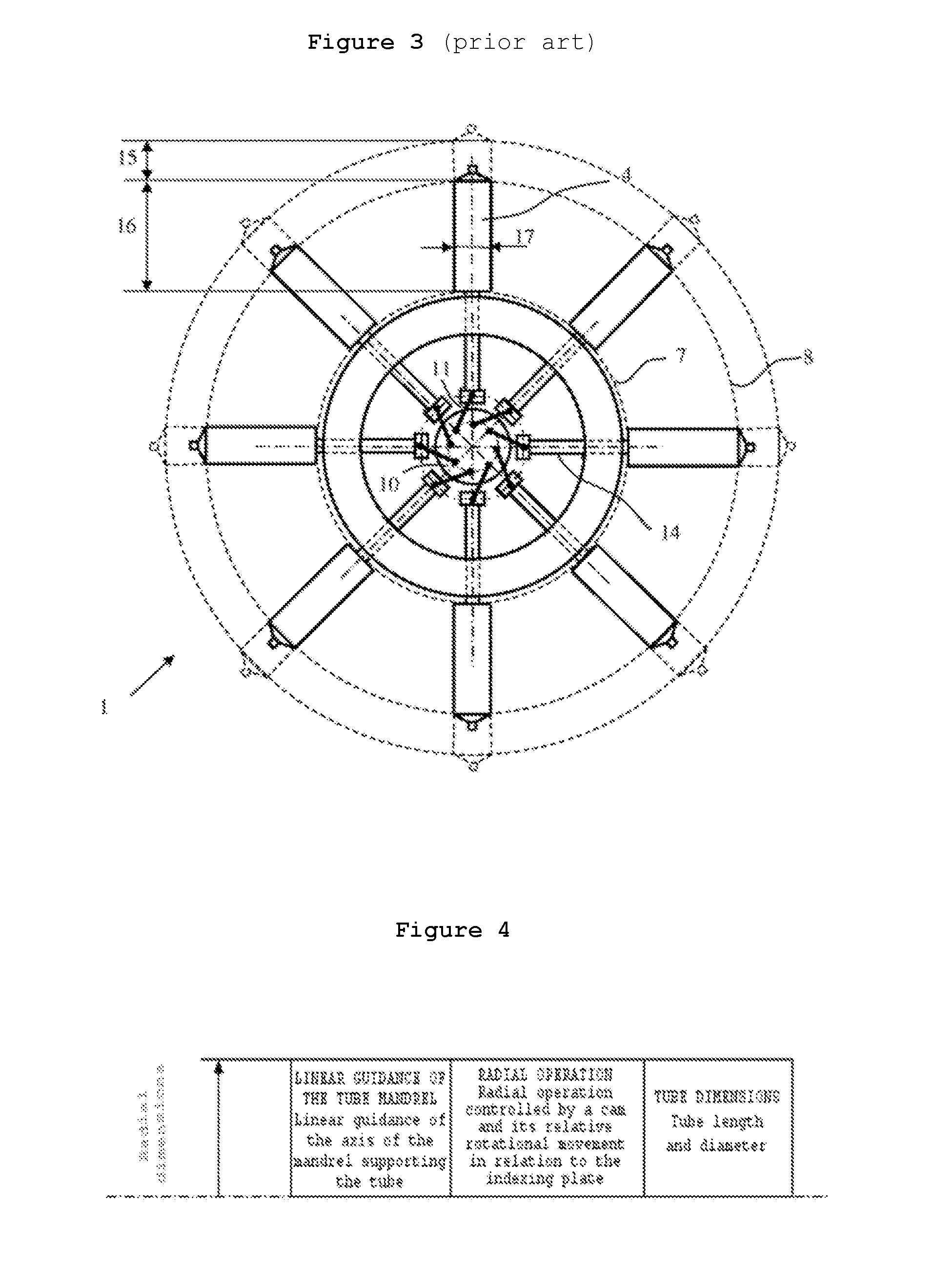
[0084]According to the concept of the invention illustrated in FIG. 4 the device is based on a radial arrangement of the following members in parallel:[0085]linear guide member 13 for mandrel 4[0086]the member actuating mandrel 4 to perform approach and withdrawal movement 15[0087]mandrel 4 and its support 14

[0088]The configuration described in FIG. 4 is particularly advantageous because the moment of inertia of the rotary assembly can be substantially reduced and as a consequence production rates can be increased through reducing indexing times.

[0089]The invention described in FIG. 4 makes it possible to bring axis of rotation 9 closer to the center of inertia of mandrels 4, thus significantly reducing the torque on the axis of the turntable during acceleration and deceleration stages. The invention makes possible a significant increase in the level of acceleration and deceleration of the turntable without creating an excessively large torque on the drive shaft. The invention can t...


PUM

PropertyMeasurementUnit
shapeaaaaaaaaaa
lengthaaaaaaaaaa
flexibleaaaaaaaaaa

Abstract

Rotary indexing device for manufacturing packaging tubes, comprising an indexing turntable (3) mounted in a rotary manner about an axis (9), and mandrels (4) and respective supports (14) secured to said turntable (3) and disposed radially with respect to said axis (9); radial actuating means (10, 11) for moving the mandrels (4) in a direction perpendicular to said axis (9) and linear guide means (13) for moving the mandrels (4) in a direction perpendicular to said axis (9); characterized in that the mandrels and respective supports (14), the radial actuating means (10, 11) and the linear guide means (13) are disposed in a direction parallel to said axis (9).

Description

CROSS-REFERENCE TO RELATED APPLICATIONS[0001]This application is the U.S. national stage of International Application No. PCT / IB2014 / 062593, filed Jun. 25, 2014, which designated the U.S. and claims foreign priority to the European patent application No. 13174868.3, filed Jul. 3, 2013, the entire contents of each of which are hereby incorporated by reference.FIELD OF THE INVENTION[0002]The invention relates to the field of devices for the manufacture of flexible packaging tubes for liquid or viscous products, and more particularly the field of packaging tubes manufactured by welding. These tubes comprise a tube body, a tube shoulder, possibly a seal closing off the opening in the shoulder and a cap.STATE OF THE ART[0003]Flexible tubes generally have two separate parts, namely a skirt or flexible cylindrical body connected to a shoulder comprising a nozzle, possibly a seal welded onto the neck, and a cap. The skirt of the tube is obtained either by extruding a tubular body, or by wel...

Claims


Application Information

Patent Timeline
Patent Type & Authority Patents(United States)
IPC IPC(8): B65G47/82B29C65/78B29C31/00B29C65/00B29D23/20B29L23/00
CPCB29C65/7885B29C31/002B29C66/5344B29C65/7882B29C66/8225B29C66/8322B29D23/20B29L2023/00B29C66/612B29C31/00
Inventor STAHL, CHRISTOPHESCHWAGER, JEAN-CLAUDEFERRIN, DIDIER
Owner AISAPACK HLDG SA
Why Eureka
Try Eureka