Lane boundary line recognition device and computer-readable storage medium storing program of recognizing lane boundary lines on roadway

a technology of boundary line recognition which is applied in the field oflane boundary line recognition devices and computer-readable storage mediums, can solve the problems of insufficient boundary line detection devices and incorrect recognition of devices, and achieve the effect of suppressing the influence of presence and increasing the accuracy of recognizing

Active Publication Date: 2017-01-10
DENSO CORP
View PDF13 Cites 1 Cited by
  • Summary
  • Abstract
  • Description
  • Claims
  • Application Information

AI Technical Summary

Benefits of technology

[0008]It is therefore desired to provide a lane boundary line recognition device capable of detecting and recognizing lane boundary lines of an own vehicle lane of a roadway, on which an own vehicle drives, with high recognition accuracy, and avoiding incorrect recognition of the lane boundary line of the own vehicle lane due to the presence of a lane boundary line of a branch road.
[0011]If the lane boundary line recognition device resets the estimated rate of change of the curvature to zero even if using a past curvature which has been calculated a predetermined-number of frame images before instead of using the currently-calculated curvature of the lane boundary line candidate, there is a possible case in which the curvature of the lane boundary line candidate to be successively calculated is shifted from the correct curvature of the white line as the lane boundary line of the own vehicle lane on the roadway due to the presence of the curvature of the white line (lane boundary line) of the branch road. In order to avoid this problem and calculate the correct curvature of the lane boundary line candidate of the own vehicle lane on the roadway, not the lane boundary line of the branch road, the lane boundary line recognition device resets the currently calculated curvature to the past curvature calculated the a predetermined-number of frame images before, and further resets the estimated rate of change of the curvature to zero. This makes it possible to suppress the influence of the presence of the lane boundary line of the branch road on the correct curvature of the lane boundary line candidate of the own vehicle lane on the roadway and increases the accuracy of recognizing the lane boundary line candidates of the own vehicle lane on the roadway.

Problems solved by technology

However, there is a possible incorrect recognition for the device to recognize a lane boundary line (or a white line) of a branch road as a lane boundary line of the own vehicle lane when using data regarding the lane boundary lines calculated at the detection timing of the branch road.
However, this is insufficient for the boundary line detection device to completely avoid the incorrect recognition of the lane boundary lines of the own vehicle lane by using previously-calculated road parameters including the past curvature of the lane boundary line.

Method used


Image

  • Lane boundary line recognition device and computer-readable storage medium storing program of recognizing lane boundary lines on roadway
  • Lane boundary line recognition device and computer-readable storage medium storing program of recognizing lane boundary lines on roadway
  • Lane boundary line recognition device and computer-readable storage medium storing program of recognizing lane boundary lines on roadway

Examples


Embodiment Construction

[0024]Hereinafter, various embodiments of the present invention will be described with reference to the accompanying drawings. In the following description of the various embodiments, like reference characters or numerals designate like or equivalent component parts throughout the several diagrams.

Exemplary Embodiment

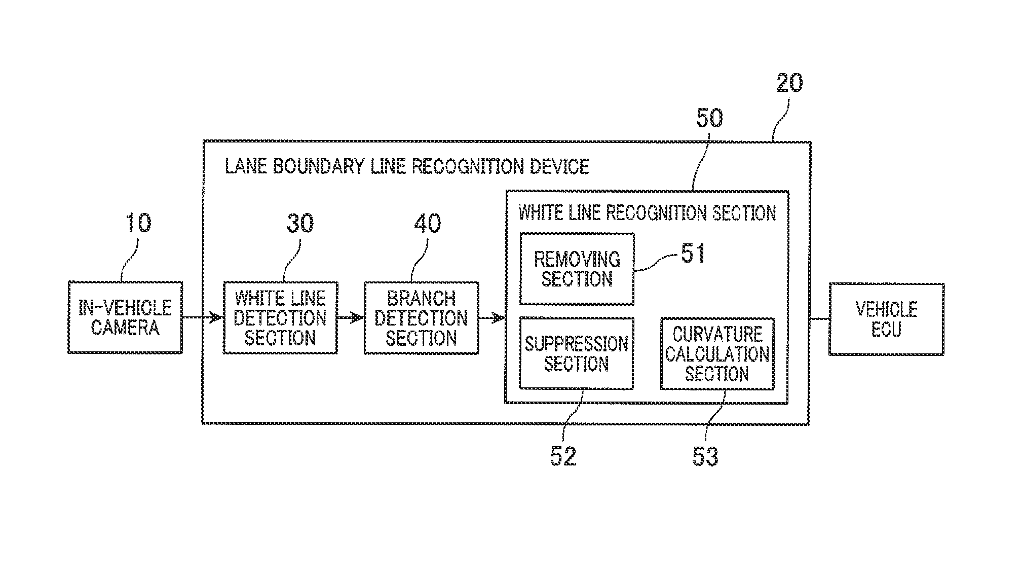
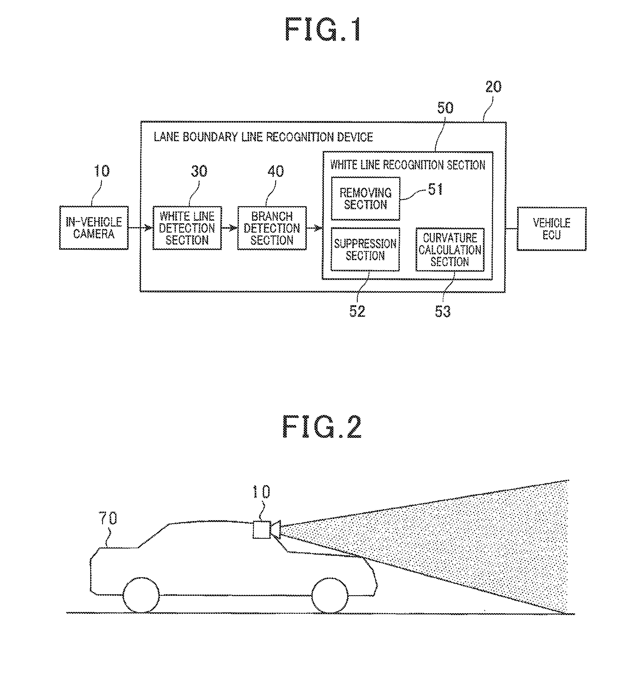
[0025]A description will be given of a lane boundary line recognition device 20 according to an exemplary embodiment with reference to FIG. 1 to FIG. 9.

[0026]FIG. 1 is a block diagram showing a structure of the lane boundary line recognition device 20 according to the exemplary embodiment. The lane boundary line recognition device 20 according to the exemplary embodiment recognizes lane boundary lines on a roadway (i.e. own vehicle lane of the roadway) on which an own vehicle 70 drives. The recognized lane boundary lines are used for a drive assist such as a lane keeping assist control (LKA control) and a lane departure warning.

[0027]A description will now be given of t...


PUM


Abstract

A lane boundary line recognition device detects lane boundary line candidates of a roadway from images captured by an in-vehicle camera, judges that the lane boundary line candidate is a lane boundary line of a branch road, and calculates a curvature of the lane boundary line candidate, and recognizes the lane boundary line based on the calculated curvature. The device removes the lane boundary line candidate, which has been judged as the lane boundary line of the branch road, is removed from a group of the lane boundary line candidates, and calculates the curvature of the lane boundary line candidate based on an estimated rate of change of the curvature. The device uses a past curvature calculated predetermined-number of images before when the lane boundary line candidate is the lane boundary line of the branch road, and resets the estimated rate of change of the curvature to zero.

Description

CROSS-REFERENCE TO RELATED APPLICATION[0001]This application is related to and claims priority from Japanese Patent Application No. 2014-142962 filed on Jul. 11, 2014, the contents of which are hereby incorporated by reference.BACKGROUND OF THE INVENTION[0002]1. Field of the Invention[0003]The present invention relates to lane boundary line recognition devices and computer-readable storage mediums for storing programs capable of recognizing lane boundary lines on a roadway on which an own vehicle drives and assisting a driver of the own vehicle in order to perform driving safely.[0004]2. Description of the Related Art[0005]There has been proposed a driver assist device which detects and recognizes lane boundary lines on an own vehicle lane of a roadway, on which an own vehicle drives, on the basis of images captured by at least an in-vehicle camera mounted on the own vehicle. The driver assist device performs the driver assist of the own vehicle on the basis of the recognized lane b...

Claims


Application Information

Patent Timeline
Patent Type & Authority Patents(United States)
IPC IPC(8): G06K9/00G06T7/20G06K9/46G06T7/60H04N7/00G06V10/44
CPCG06K9/00798G06K9/4604G06T7/20G06T7/60G06T2207/30256G06V20/588G06V10/44
Inventor MAEDA, YUUKAWASAKI, NAOKIKUMANO, SYUNYASUZUKI, SHUNSUKE
Owner DENSO CORP
Why Eureka
Try Eureka