
Handle-dampening lacrosse stick

a technology of lacrosse stick and handle, which is applied in the field of lacrosse sticks, can solve the problems of difficult to catch and control thrown balls, and achieve the effect of discharging some of the energy of thrown balls

Inactive Publication Date: 2017-01-24
WM T BURNETT IP
View PDF18 Cites 0 Cited by
  • Summary
  • Abstract
  • Description
  • Claims
  • Application Information

AI Technical Summary

Benefits of technology

[0009]It is, therefore, an object of the present invention to provide a method and apparatus for dampening the rebound of a lacrosse head and pocket after the pocket has had force applied to it by, for example, a thrown lacrosse ball.
[0010]Unlike the substantially rigid lacrosse head frames of the prior art, which attach pocket thread to unforgiving, rigid structures, the present invention provides a flexible, energy-absorbing elastomer insert within a specially-formed handle that exposes the elastomer insert to the socket (throat and / or stop member) of the head, where the head and handle meet. The material within the handle and abutting the socket throat / stop member dampens the recoil of an otherwise rigid head and handle. The flexibility of the insert material produces a “give” that minimizes the rebound of a pocket after being impacted by a ball. This pocket dampening suppresses movement of the ball and makes the ball easier to control and to retain in the pocket, a basic fundamental of the game. The precise location of the dampening material on the lacrosse head may be varied to control the degree of pocket “give” in response to, for example, the force on the pocket created by a ball impacting the pocket during a catch or swinging in the pocket during quick, side to side rotations of the head, known as cradling, another basic fundamental of the game.
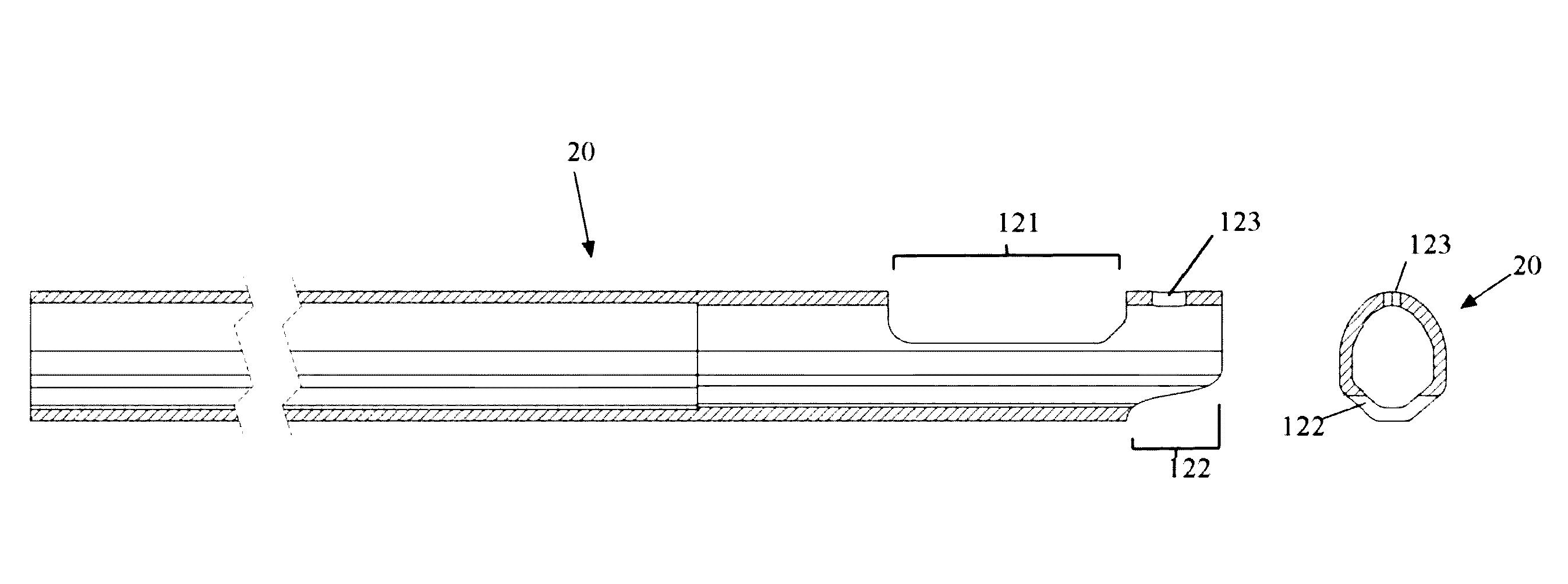
[0012]Alternate embodiments are herein described in which portions of the socket wall are replaced by one or more elastomeric wall sections, preferably a first portion on the back side of the throat and a second portion on the front side of the stop member, offset from the first portion inwardly toward the pocket. This may be accomplished by molding or cutting windows, cavities or receptacles, or otherwise omitting areas within the socket, and overmolding or insetting the resilient member(s) such that they fill the cavities made in the socket. The resilient member(s) are contoured to fill the areas of omitted socket so as to be flush with the inside surface of the socket. The throat is aligned with the socket such that the shaft passes through the throat when received in the socket. The shaft inserted into the socket firstly engages the resilient insert in the omitted portion on the back side of the socket at the throat, and optionally secondly engages the second resilient insert offset inwardly toward the pocket on the front side of the stop member. When a force is applied to the front side of the head by, for example, a ball entering the pocket, the head leverages about the socket and compresses the first resilient member against the underside of the shaft, while optionally simultaneously compressing the second resilient against the topside of the shaft. This affords a degree of freedom and allows the head to rotate backward about an axis perpendicular to the shaft and thereby dissipate some of the energy of the thrown ball rather than returning that energy to the ball.

Problems solved by technology

This makes it difficult to catch and control thrown balls, particularly balls thrown at high velocity.

Method used


Image

  • Handle-dampening lacrosse stick
  • Handle-dampening lacrosse stick
  • Handle-dampening lacrosse stick

Examples


Embodiment Construction

[0037]The present invention is an apparatus and method for dampening the rebound of a lacrosse head after force has been applied to it by, for example, a lacrosse ball entering and striking its pocket.

[0038]FIG. 2 is an exploded rear view and FIG. 3 is an enlarged side view of an exemplary embodiment of the invention designed for use with a conventional lacrosse head 10 such as, for example, depicted in FIG. 1. In this embodiment a lacrosse handle 20 is modified to accept a distal elastomeric insert 30. The handle 20 with insert 30 in place is then received within the socket 11 of the head 10 as described above. The socket 11 forms a collar about the shaft 20 with walls conforming to those of the shaft 20 (which is typically rounded hexagonal, octagonal, oval or circular cross section or any combination thereof) to secure the shaft within the socket and the head to the shaft. The shaft 20 is inserted into the socket 11 until the end of the shaft abuts the stop member 18 (see FIGS. 1...


PUM

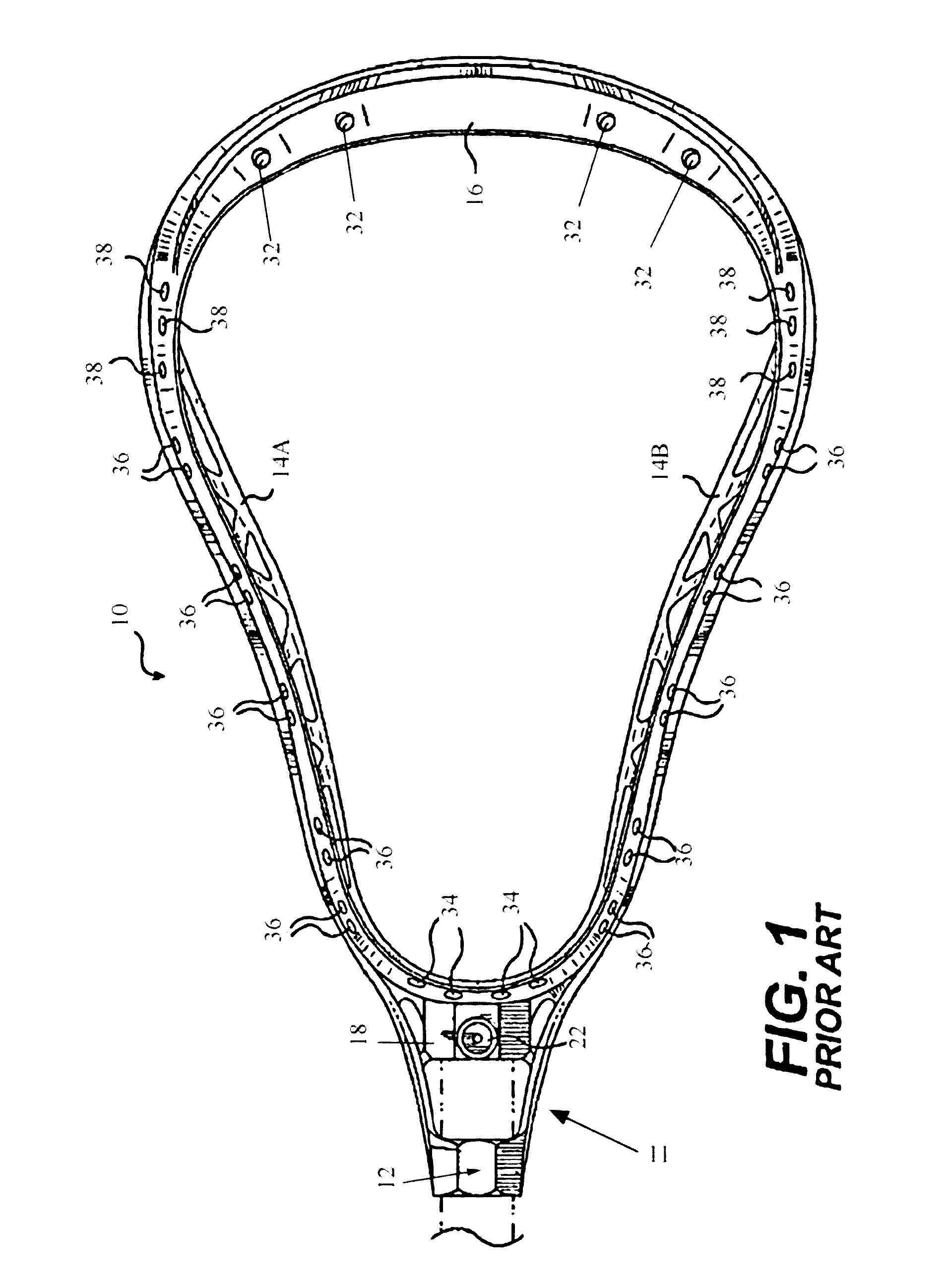
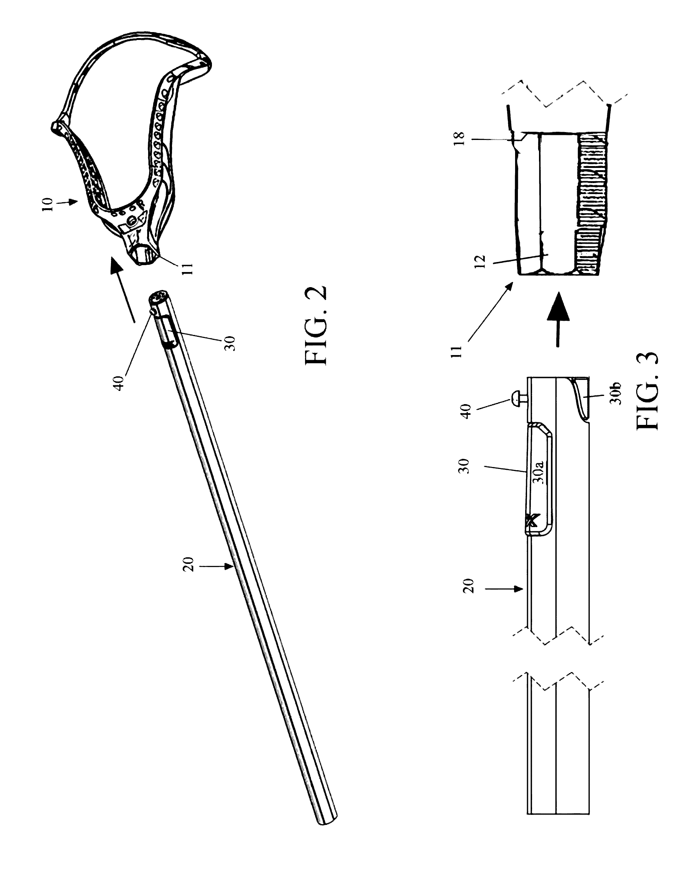

Abstract

A lacrosse stick for reducing the rebound of a ball caught therein. The head of the lacrosse stick has a socket for receiving the shaft, and incorporates one or a plurality of flexible elastomer pads within or as part of the handle or socket, where the head and handle meet, to damp impact and rebound. The flexibility of the damping pads produces a “give” that minimizes the rebound of a pocket after being impacted by a ball. This pocket dampening limits the movement of the ball and makes the ball easier to control and to retain in the pocket. The precise location of the dampening material on the lacrosse head may be varied to control the degree of pocket “give” in response to, for example, the force on the pocket created by a ball impacting the pocket during a catch or swinging in the pocket during cradling.

Description

CROSS-REFERENCE TO RELATED APPLICATIONS[0001]The present application claims priority to U.S. Provisional Patent Application Ser. No. 61 / 640,358 filed 30 Apr. 2012, and is a continuation-in-part of U.S. application Ser. No. 13 / 267,537, which derives priority from U.S. Provisional Application 61 / 390,339 filed Oct. 6, 2010.BACKGROUND OF THE INVENTION[0002]1. Field of the Invention[0003]The present invention relates generally to lacrosse sticks, and more particularly to an apparatus and method for dampening the rebound of a lacrosse stick head pocket after the pocket has had force applied to it by, for example, a caught lacrosse ball.[0004]2. Description of the Background[0005]FIG. 1 illustrates a conventional molded-head lacrosse stick. As shown, a typical lacrosse stick includes a handle or shaft (dashed lines) and a double-wall synthetic head 10. Head 10 includes a generally V-shaped frame having two sidewalls 14A, 14B joined by a socket 11 at the narrow end of the “V” for receiving ...

Claims


Application Information

Patent Timeline
Patent Type & Authority Patents(United States)
IPC IPC(8): A63B65/12
CPCA63B60/06A63B59/20A63B60/08A63B60/10A63B60/54A63B60/26A63B60/50A63B60/00
Inventor LIGNELLI, JOANNAABDELMALEK, ANTHONYSCHMITTDIEL, MIKE
Owner WM T BURNETT IP
Learn More