
An Improved Ultrathin Loop Heat Pipe

A loop heat pipe, an improved technology, used in indirect heat exchangers, lighting and heating equipment, etc., can solve the problems of large temperature and pressure fluctuations, high liquid cooling cost, small contact area, etc. The fluctuation of the machine is small, the operation is stable and reliable, and the effect of reducing the manufacturing cost

Active Publication Date: 2017-10-20
广东省华创热控科技有限公司
View PDF1 Cites 0 Cited by
  • Summary
  • Abstract
  • Description
  • Claims
  • Application Information

AI Technical Summary

Problems solved by technology

In recent years, due to the birth of high heat flux components, equipment, etc., traditional air-cooled heat dissipation has reached the heat dissipation limit and is far from meeting the heat dissipation requirements. Liquid-cooled heat dissipation has also been difficult due to its high cost, complex system, and leakage. widely used
[0003] However, the traditional loop heat pipe still has the following defects: 1. The evaporation part of the heat pipe is mostly in the shape of a circular tube, which has a small contact area with the heat source and the heat dissipation effect is poor; 2. The sintered capillary structure is used in the heat pipe, which causes the working fluid to encounter 3. The heat pipe needs to sinter the capillary structure to the tube filling material, which is complex in structure, inconvenient to process, and heavy in weight; 4. Most of the heat pipes are circular tubes, which causes heat pipes and The fit of the heat source is not high, and the installation is inconvenient; 5. The same heat pipe is only suitable for electric vehicles or the electronics industry or the aerospace industry, and cannot meet the requirements of the electric vehicle, electronics industry, aerospace industry, and equipment manufacturing industries at the same time. Therefore, the versatility of the heat pipe is poor and the scope of application is small
Although this invention patent solves the above problems to a certain extent, it still has some other defects, such as the unstable flow of the gas-liquid two-phase working fluid, large fluctuations in temperature and pressure during operation, and high thermal resistance during operation.

Method used


Image

  • An Improved Ultrathin Loop Heat Pipe
  • An Improved Ultrathin Loop Heat Pipe
  • An Improved Ultrathin Loop Heat Pipe

Examples


Embodiment Construction

[0027] The present invention will be further described below in conjunction with drawings and embodiments.

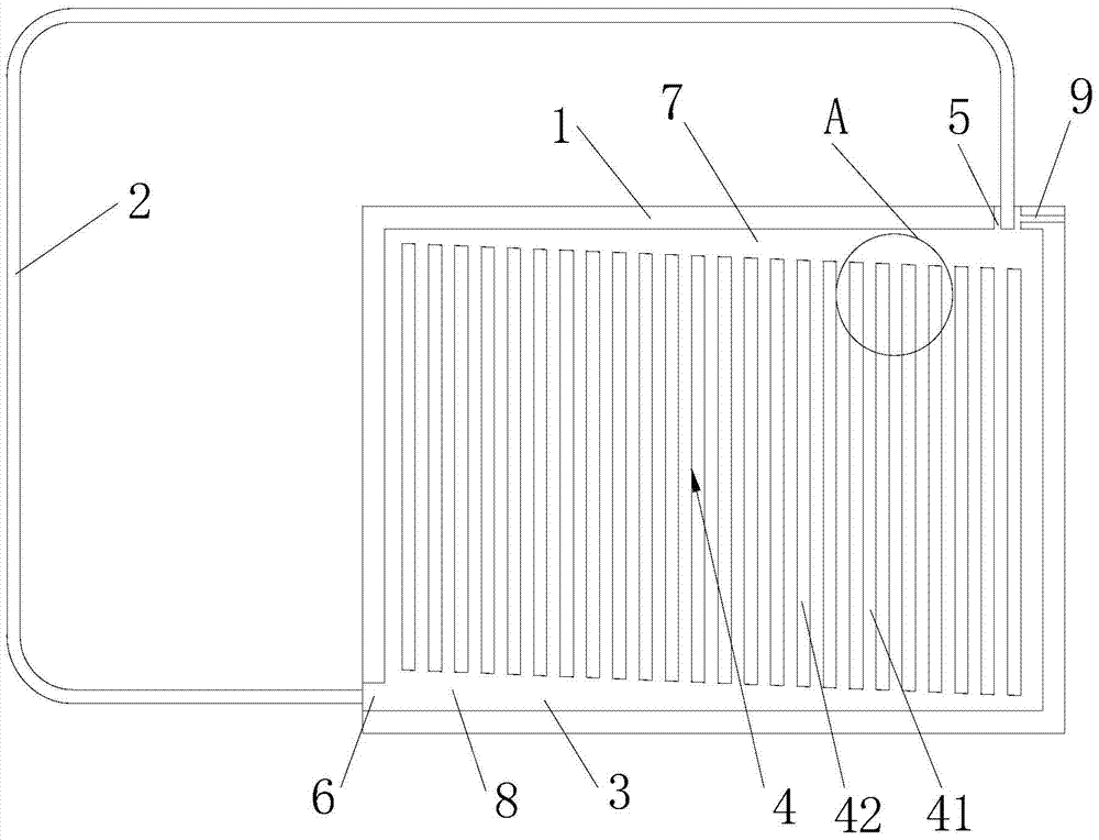
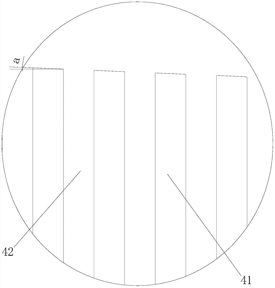
[0028] Such as Figure 1 to Figure 3 The improved ultra-thin loop heat pipe shown includes a metal base plate 1, a metal cover plate and an elbow 2, the metal base plate 1 is provided with a groove 3, and the edge of the metal base plate 1 is sealed with the edge of the metal cover plate connected, the metal cover plate covers the groove 3, the groove 3 is provided with a channel 4 with capillary action, and the two ends of the metal substrate 1 are respectively provided with a first communication port 5 and a second communication port 6 , the first communication port 5 and the second communication port 6 communicate with the groove 3, and the two ends of the elbow 2 are respectively connected to the first communication port 5 and the second communication port 6; the channels 4 are parallel Quadrilateral, above the channel 4 there is a vapor pool 7 with a gradually cha...


PUM


Abstract

The invention discloses an improved ultrathin loop heat pipe. The improved ultrathin loop heat pipe comprises a metal base plate, a metal cover plate and an elbow pipe, wherein a groove is formed in the metal base plate, the edge of the metal base plate is connected with the edge of the metal cover plate in sealed mode, the metal cover plate covers the groove, a channel is formed in the groove, a first communication port and a second communication port which are communicated with the groove are respectively formed in two ends of the metal base plate, two ends of the elbow pipe are respectively connected with the first communication port and the second communication port, the channel is in a parallelogram shape, a steam pond gradually varied in width is arranged above the channel, a liquid pond gradually varied in width is arranged below the channel, and the steam pond and the liquid pond are communicated through the channel. The improved ultrathin loop heat pipe can effectively obstruct back flushing of gaseous working media, reduces instability in two phase flowing, can be rapidly started under lower start temperature, is low in temperature and pressure fluctuation in running, and achieves lower running heat resistance and high work efficiency for a system.

Description

technical field [0001] The invention relates to heat transfer equipment technology, in particular to an improved ultra-thin loop heat pipe. Background technique [0002] With the rapid development of industries such as electric vehicles, electronics, aerospace and equipment manufacturing, modern industries have higher and higher requirements for heat dissipation. In recent years, due to the birth of high heat flux components, equipment, etc., traditional air-cooled heat dissipation has reached the heat dissipation limit and is far from meeting the heat dissipation requirements. Liquid-cooled heat dissipation has also been difficult due to its high cost, complex system, and leakage. be widely applied. As an efficient phase change heat transfer device, the loop heat pipe mainly transfers heat through the two-phase change of the heat transfer fluid, and is becoming more and more important in the heat dissipation system. At present, loop-type gravity heat pipes, pulsating heat...

Claims


Application Information

Patent Timeline
Patent Type & Authority Patents(China)
IPC IPC(8): F28D15/02
CPCF28D15/0266
Inventor 汪双凤洪思慧唐永乐张新强郝世杰
Owner 广东省华创热控科技有限公司
Learn More