

Vehicle body end section structure
a technology for end sections and vehicles, applied in the direction of superstructure subunits, bumpers, vehicle components, etc., can solve the problems of crash box folding, etc., and achieve the effect of suppressing the adverse impact of the energy absorption strok
- Summary
- Abstract
- Description
- Claims
- Application Information
AI Technical Summary
Benefits of technology
Problems solved by technology
Method used
Image

Examples
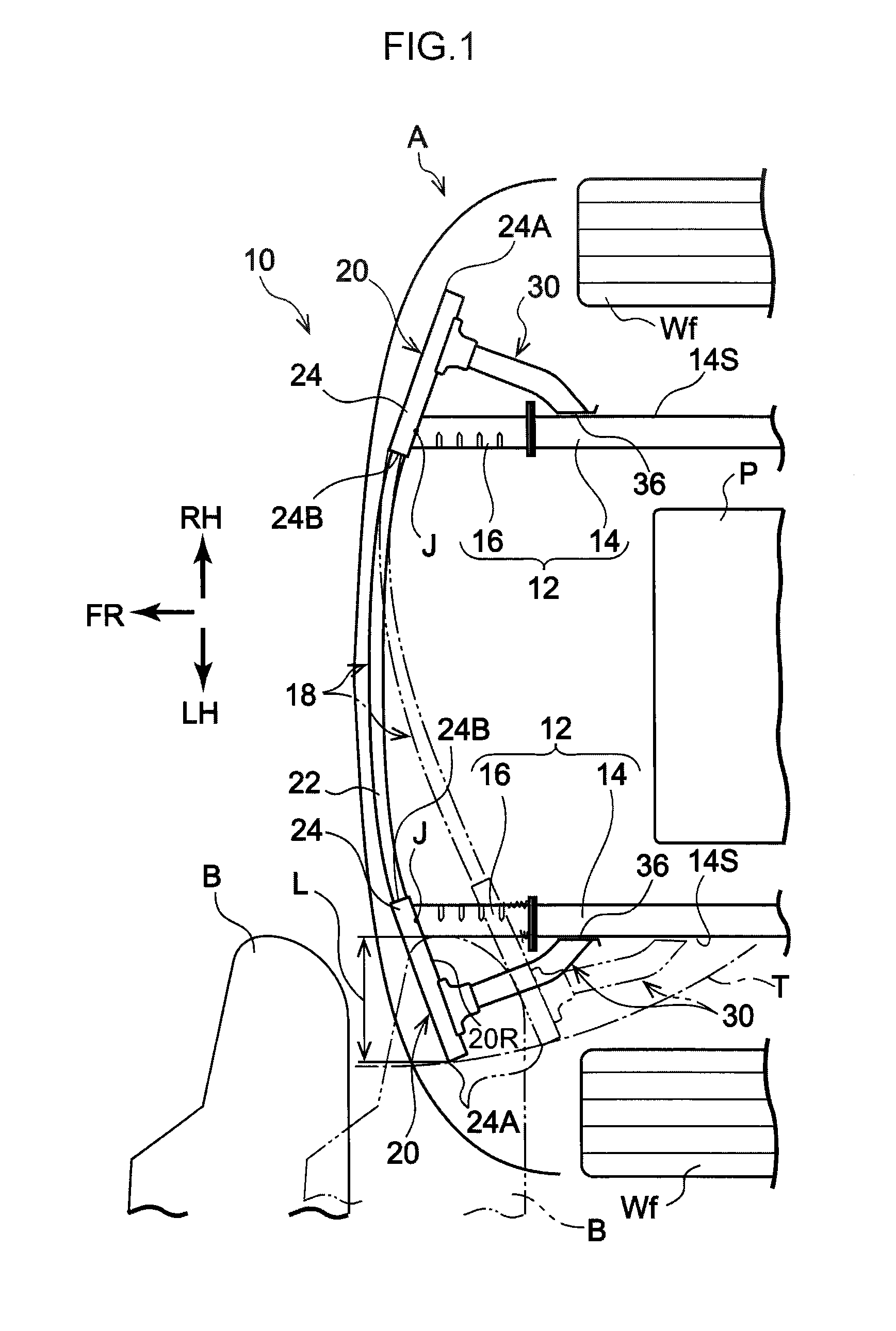
first exemplary embodiment
[0112
[0113]Bumper Reinforcement
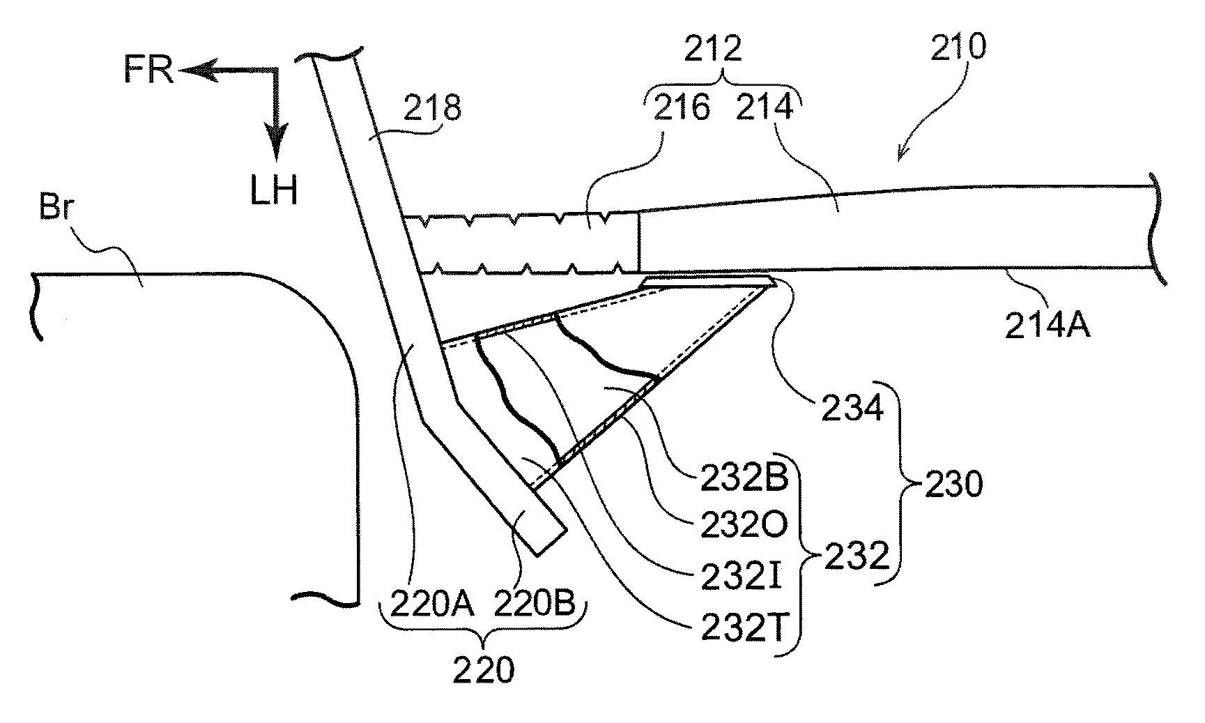
[0114]In the present exemplary embodiment, the bumper reinforcement 18 is mainly configured by a reinforcement body 22 serving as a bumper frame body, and a pair of extensions 24 that serve as extension members and configure the respective jutting-out portions 20.
[0115]Reinforcement Body
[0116]Although not illustrated in the drawings, the reinforcement body 22 is formed with a closed cross-section structure, for example by extrusion molding aluminum, or an aluminum alloy. In the present exemplary embodiment, the cross-section profile of the reinforcement body 22 is configured with a profile of three rectangular shaped frames stacked one above the other (a cross-section profile resembling a rectangle divided into three from top-to-bottom). Both length direction end portions of the reinforcement body 22 configure part of the respective jutting-out portions 20.
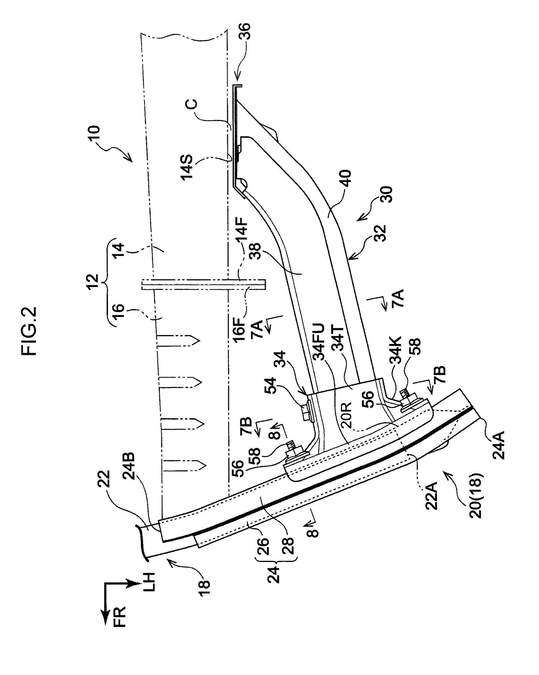
[0117]Extensions
[0118]As illustrated in FIG. 2, each extension 24 is fixed to a length direction ...
second exemplary embodiment
[0180
[0181]Explanation follows regarding a vehicle body front section structure 60 according to a second exemplary embodiment of the present invention, with reference to FIG. 11 and FIG. 12. FIG. 11 is an exploded perspective view corresponding to FIG. 6, illustrating a slide spacer 62 serving as a spacer member configuring the vehicle body front section structure 60. The vehicle body front section structure 60 has similar configuration to the vehicle body front section structure 10 according to the first exemplary embodiment, with the exception of the slide spacer 62 provided in place of the slide spacer 30, and a retaining structure of the slide spacer 62 with respect to the front side member 14.
[0182]As illustrated in FIG. 11, the slide spacer 62 includes a slide plate portion 64 in place of the slide plate portion 36. The slide plate portion 64 is configured including a slide plate 66 facing the side face 14S of the front side member 14 across the gap C, and a fastened member 68...
third exemplary embodiment
[0194
[0195]Explanation follows regarding a vehicle body front section structure 80 according to a third exemplary embodiment of the present invention, with reference to FIG. 13A to FIG. 14B. FIG. 13A is a plan view schematically illustrating a partial configuration of a left end side of the vehicle body front section structure 80, and FIG. 13B is a side view schematically illustrating a partial configuration of the vehicle body front section structure 80. The vehicle body front section structure 80 has similar configuration to the vehicle body front section structure 10 according to the first exemplary embodiment, with the exception of a stopper structure 82 that restricts sliding of the slide spacer 30. Detailed explanation follows thereof.
[0196]The stopper structure 82 includes a stopped member 84, serving as an abutting portion, provided at a rear end side of the slide spacer 30. The stopped member 84 is configured so as to move toward the rear with respect to the front side memb...
PUM
 Abstract
Description
Claims
Application Information