
Solar cell apparatus and method of fabricating the same

a solar cell and apparatus technology, applied in electrical apparatus, photovoltaic energy generation, semiconductor devices, etc., can solve problems such as deteriorating process efficiency, achieve the effect of preventing exposure, improving the aesthetics of solar cell apparatus according to the embodiment, and being easy to apply

Inactive Publication Date: 2017-01-24
LG INNOTEK CO LTD
View PDF20 Cites 2 Cited by
  • Summary
  • Abstract
  • Description
  • Claims
  • Application Information

AI Technical Summary

Benefits of technology

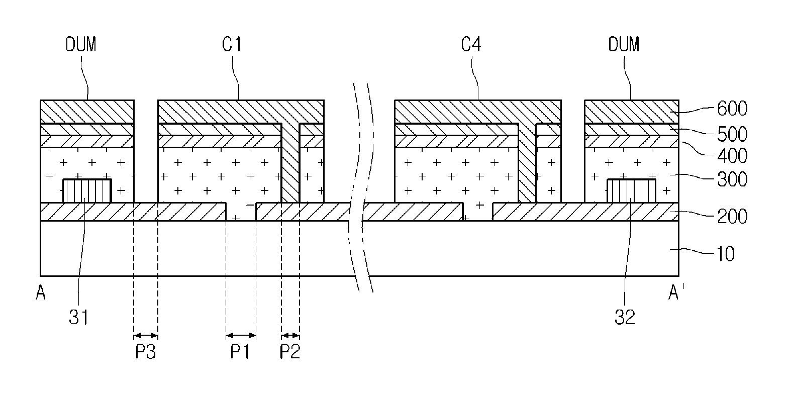
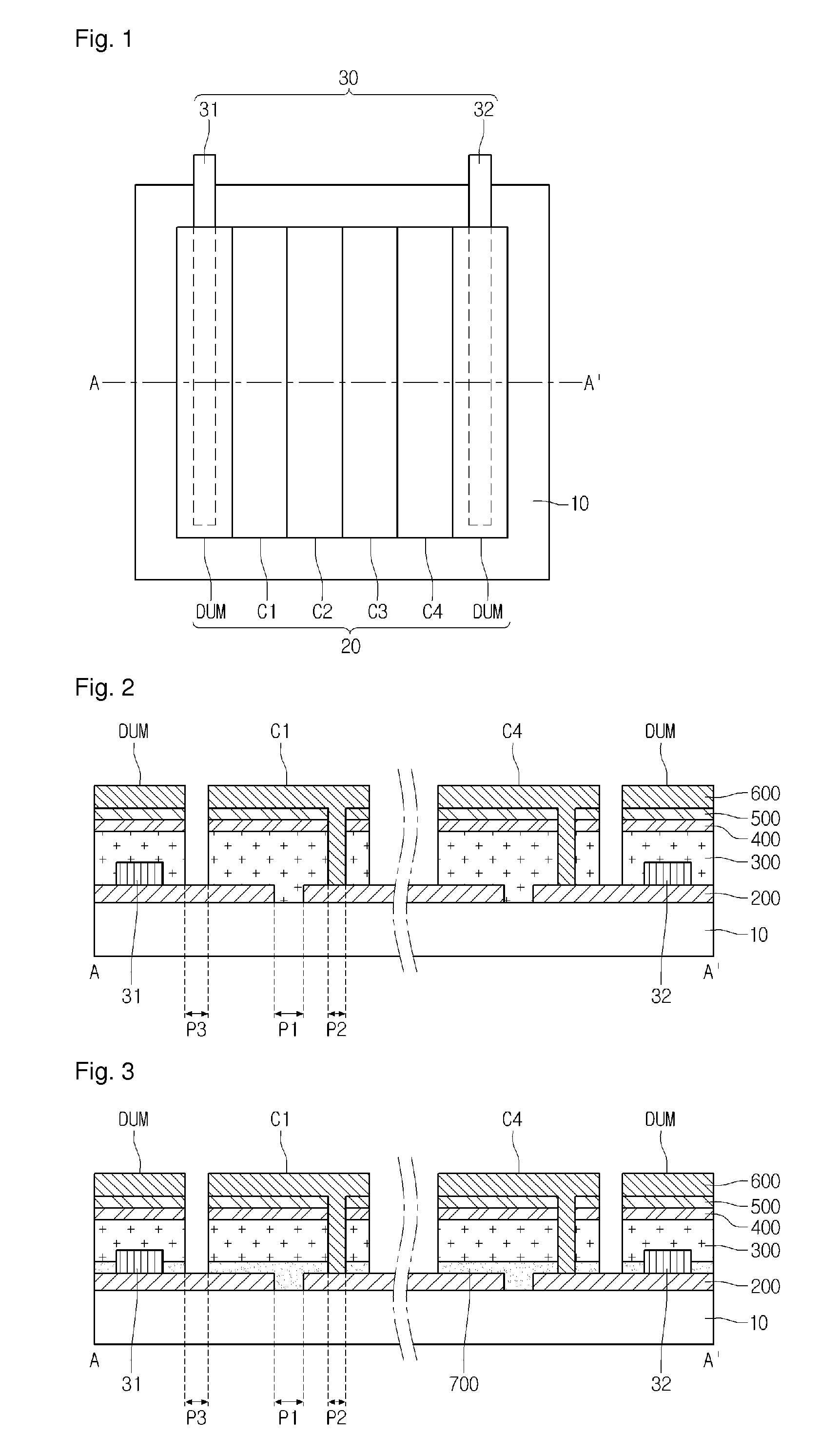
[0010]In the solar cell apparatus according to the embodiment, the bus bar is disposed between the support substrate and the dummy. Accordingly, the solar cell apparatus according to the embodiment can prevent exposure of the bus bar to the outside without using a separate shielding unit. Thus, an aesthetic feature of the solar cell apparatus according to the embodiment can be significantly improved, and the solar cell apparatus can be easily applied to a curtain wall solar cell module, for example, used on an outer wall of a building.
[0011]In addition, the bus bar is formed in a non-active area (NAA) other than an active area (AA) where the solar cells are formed, for example, in the dummy. Thus, the solar cell apparatus can increase the active area. Accordingly, an efficiency of the solar cell apparatus can be increased.
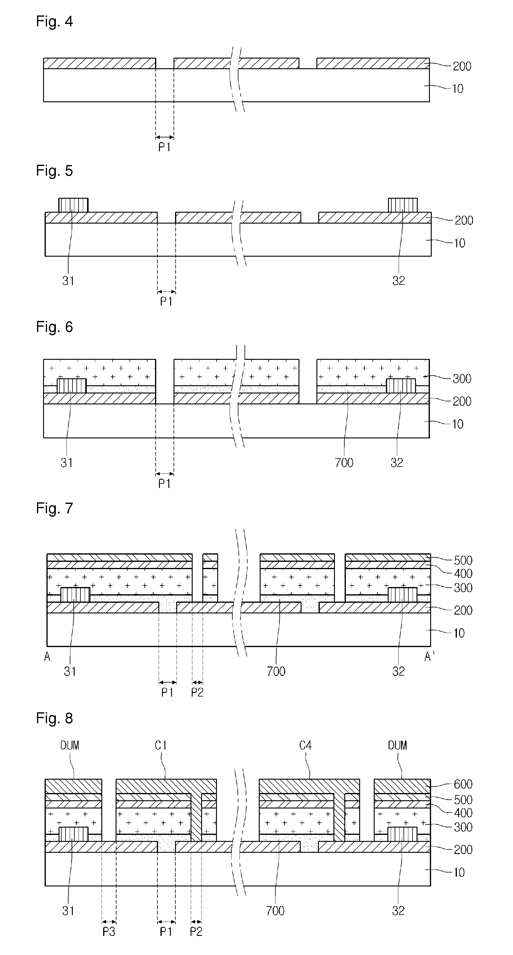
[0012]In the method of fabricating the solar cell apparatus according to the embodiment, the bus bar is formed on the back electrode layer before the light absorbing layer is formed. Thus, a contact resistance layer, which may be generated in the light absorbing layer fabricating process, is not formed on an interfacial surface between the back electrode layer and the bus bar. Accordingly, electron migration may be facilitated between the back electrode layer and the bus bar, and a photoelectric conversion efficiency of the solar cell apparatus can be improved. In addition, a bonding strength between the back electrode layer and the bus bar can be significantly improved.

Problems solved by technology

The bus bar fabricated through the method has a weak bonding strength to the solar cell module, and also requires an additional process for improving an outer appearance of the solar cell module, deteriorating process efficiency.

Method used


Image

  • Solar cell apparatus and method of fabricating the same
  • Solar cell apparatus and method of fabricating the same
  • Solar cell apparatus and method of fabricating the same

Examples


Embodiment Construction

[0016]In the description of the embodiments, it will be understood that when a substrate, a layer, a film or an electrode is referred to as being “on” or “under” another substrate, another layer, another film or another electrode, it can be “directly” or “indirectly” on the other substrate, the other layer, the other film, or the other electrode, or one or more intervening layers may also be present. Such a position of the layer has been described with reference to the drawings. The size of the elements shown in the drawings may be exaggerated for the purpose of explanation and may not utterly reflect the actual size.

[0017]FIG. 1 is a plan view illustrating an upper surface of a solar cell apparatus according to an embodiment. FIGS. 2 and 3 are sectional views taken along line A-A′ of FIG. 1.

[0018]Referring to FIG. 1, the solar cell apparatus according to the embodiment includes a support substrate 10, a solar cell module 20, and a bus bar 30.

[0019]The support plate 10 has a plate s...


PUM


Abstract

Disclosed are a solar cell apparatus, and a method of fabricating the same. The solar cell apparatus includes: dummy parts disposed on a support substrate; a plurality of solar cells disposed on the support substrate and disposed between the dummy parts; and a bus bar electrically connected to the solar cells and disposed between the support substrate and the dummy parts. Each of the solar cells and the dummy parts has a back electrode layer, a light absorbing layer, and a front electrode layer sequentially disposed on the support substrate.

Description

CROSS-REFERENCE TO RELATED APPLICATIONS[0001]This application is the U.S. national stage application of International Patent Application No. PCT / KR2012 / 008480, filed Oct. 17, 2012, which claims priority to Korean Application No. 10-2011-0106371, filed Oct. 18, 2011, the disclosures of each of which are incorporated herein by reference in their entirety.TECHNICAL FIELD[0002]The embodiment relates a solar cell apparatus and a method of fabricating the same.BACKGROUND ART[0003]A solar cell may be defined as a device for converting light energy into electric energy by using a photovoltaic effect where electrons are produced by exposing a p-n junction diode to light. Such solar cells may be classified into a silicon solar cell, a compound semiconductor solar cell, a dye-sensitized solar cell, and an organic solar cell according to a material used as a junction diode.[0004]A minimum unit of a solar cell is a cell, and a voltage produced by one solar cell is generally as low as approximate...

Claims


Application Information

Patent Timeline
Patent Type & Authority Patents(United States)
IPC IPC(8): H01L31/046H01L31/02H01L27/30
CPCH01L31/0201H01L27/302H01L31/046Y02E10/542H10K30/57H01L31/0465H01L31/042H01L31/0224H01L31/18
Inventor SHIN, MIN JUNG
Owner LG INNOTEK CO LTD
Learn More