Baluster connector

a technology of connectors and balusters, applied in the direction of balusters, building types, constructions, etc., can solve the problems of insecure mounting between the baluster and the rail, waste of material in the center of the baluster, and not always satisfying the consumer's desire for a connection

Active Publication Date: 2017-01-31
DECKORATORS
View PDF17 Cites 23 Cited by
  • Summary
  • Abstract
  • Description
  • Claims
  • Application Information

AI Technical Summary

Problems solved by technology

The typical baluster connector does not always satisfy the consumer's desire for a connection that is difficult to disconnect.
The extruded boss-type connection results in a secure connection but can also cause wasted material in the center of the baluster since the baluster is typically connected at each end to the railing.
In addition, pre-formed balusters with connection mounts do not typically account for manufacturing tolerances of the baluster, potentially resulting in an insecure mount between the baluster and the rail.
However, it also did not account for the manufacturing tolerance of the hollow baluster, causing some difficulties in achieving a consistent fit between a baluster and a baluster connector.
For example, if the baluster-connector fit is too tight, it can be difficult to fully seat the baluster on the connector.
Further, when the baluster was driven onto the connector, at times it would shave off a thin piece of the plastic bosses, resulting in an unattractive splay of plastic shavings at the ends of the baluster.

Method used


Image

  • Baluster connector
  • Baluster connector
  • Baluster connector

Examples


Embodiment Construction

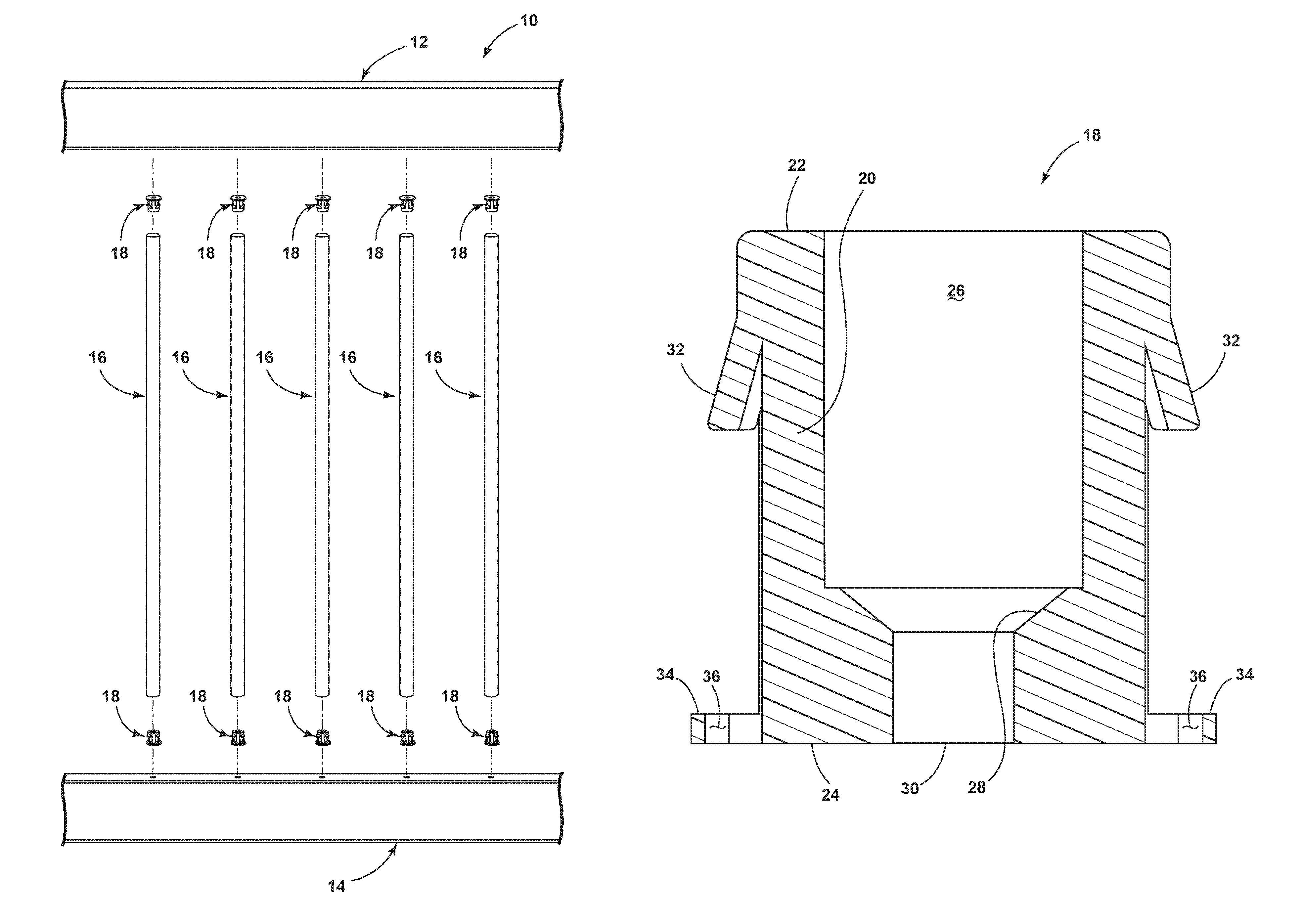
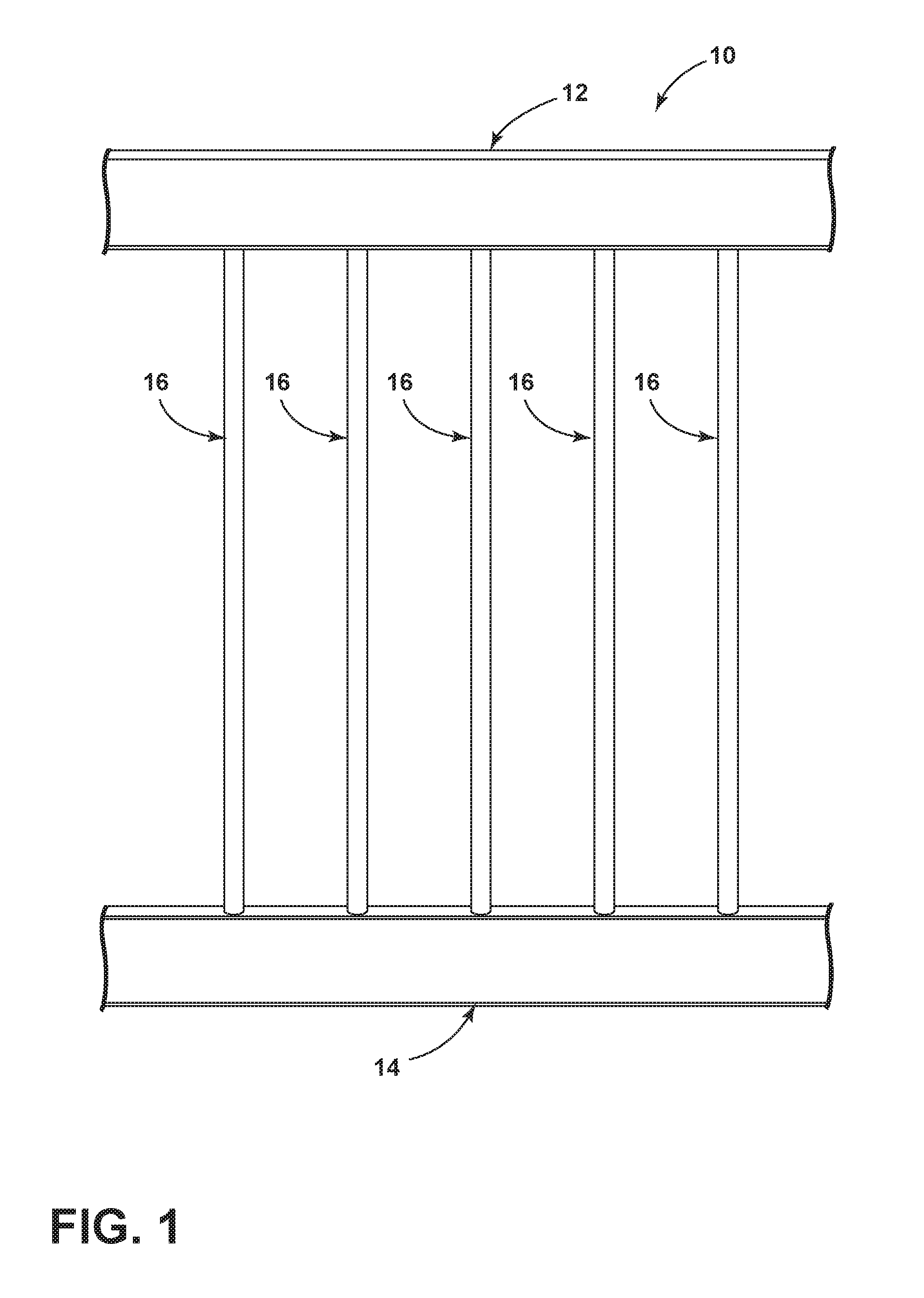
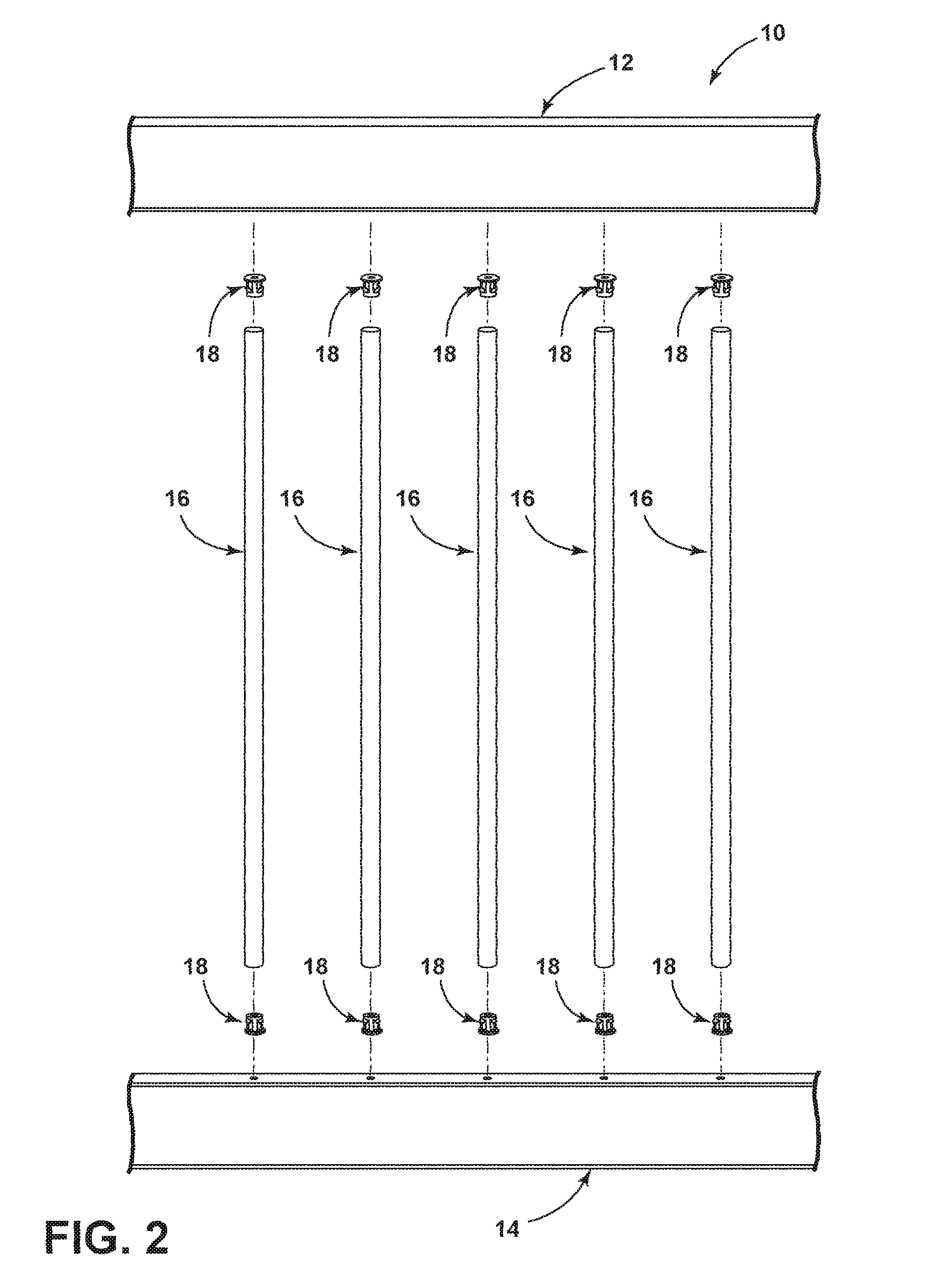
[0016]Turning now to the drawings, and to FIGS. 1-2 in particular, the invention relates generally to railing systems 10, shown by example in FIGS. 1-2, which typically have a top rail 12, a bottom rail 14, a plurality of balusters 16 spanning a vertical distance between the top rail 12 and bottom rail 14. In some cases, the railing system 10 can only have a top rail 12, and the balusters 16 are connected directly to a floor surface (not shown in the exemplary railing systems shown in FIGS. 1-2). In these figures, a plurality of connectors 18 are shown for interconnecting each baluster 16 to a corresponding top rail 12 or bottom rail 14 of the railing system 10.

[0017]The connector 18 is shown by example in greater detail in FIG. 3, and with a vertical-cross-sectional view through lines IV-IV of the connector 18 shown in FIG. 4. The connector 18 generally has a body 20 having a first end 22 and a second end 24. Although the body 20 is shown generally as a cylindrical member having a ...


PUM


Abstract

A baluster connector for interconnecting a baluster with a hollow end to a portion of a railing system by a fastener having a shaft and a head. The body portion can have an opening of sufficient size to pass the head of the fastener toward the second end of the body to seat against a necked-down portion within the interior of the body. Biasing flanges can extend away from the body to provide resistance when the body is positioned within a hollow end of a baluster.

Description

CROSS-REFERENCE TO RELATED APPLICATIONS[0001]This application claims the benefit of U.S. Provisional Patent Application No. 62 / 088,092, filed Dec. 5, 2014, which is incorporated herein by reference in its entirety.BACKGROUND OF THE INVENTION[0002]Railings are ubiquitous in commercial and residential building projects which include at least one railing and several balusters extending therebetween. A railing can be disposed horizontally or angularly, depending on whether the railing is located adjacent to a floor surface, a ramp or a stairway. Conventional balusters are attached to a railing by a bracket or a connector by threaded fasteners, or by extruding a connectable section into the center of the hollow baluster, such as a screw boss supported within a hollow baluster by connecting struts.[0003]The typical baluster connector does not always satisfy the consumer's desire for a connection that is difficult to disconnect. The extruded boss-type connection results in a secure connect...

Claims


Application Information

Patent Timeline
Patent Type & Authority Patents(United States)
IPC IPC(8): E04H17/14E04F11/18
CPCE04H17/1443E04F11/1842E04F2011/1827E04H2017/1469E04H2017/1482E04H17/1447E04H17/1439E04H17/1469E04H17/1482
Inventor MILANOWSKI, DANIEL J.
Owner DECKORATORS
Why Eureka
Try Eureka