Magnetic vibration isolation mount and method

a magnetic vibration and isolation mount technology, applied in the field of magnetic fields, can solve problems such as different problems and weaknesses, and achieve the effects of simple and sturdy, and reducing the transmission of vibration energy

Active Publication Date: 2017-01-31
SMITH KYLE
View PDF6 Cites 8 Cited by
  • Summary
  • Abstract
  • Description
  • Claims
  • Application Information

AI Technical Summary

Benefits of technology

[0010]The invention may be conceptualized as a mount that will provide a dampening effect between two objects or members that are joined together. The general idea is that this mounting device will give a simple, sturdy and effective means of joining two surfaces or objects with the transfer of vibration minimized from the first member to the second member. The magnetic vibration isolation mount comprises a first and second mounting means for mounting the first and second member respectively. Magnets are arranged between the first and second mounting means and are coupled to each member, wherein the magnets are arranged in a way that provides an opposing magnetic force between the two members.
[0011]The invention may also be conceptualized as a method as a vibration dampening or isolation method. The method controls the amount of vibration that is transmitted from the first member to the second member when both members have the opposing magnets between the two members. The magnet arrangement between the two members provides a delay and reduction in the transmission of vibration energy between the two members. The method comprises the steps of (1) sensing the vibration energy and force in one member; (2) applying a force on the second member in response to the sensed vibrational energy in the first member in order to reduce vibrations; (3) allowing for the storage of energy during normal vibrations of the first member in order to have the power storage necessary to efficiently counteract force with the second member from an unusually violent sensed vibration episode of the first member.

Problems solved by technology

These vibration dampening devices range from simple spring based systems to complex elastomeric devices, however they all have different issues and weaknesses.

Method used


Image

  • Magnetic vibration isolation mount and method
  • Magnetic vibration isolation mount and method
  • Magnetic vibration isolation mount and method

Examples


Embodiment Construction

[0019]In the following detailed description of the preferred embodiments, reference is made to the accompanying drawings which form a part hereof, and within which are shown by way of illustration specific embodiments by which the invention may be practiced. It is understood that other embodiments may be utilized and structural changes may be made without departing from the scope of the invention.

[0020]Turning now to the drawings wherein like numbers refer to like features throughout the drawings, the present invention comprises a magnetic vibration isolation mount.

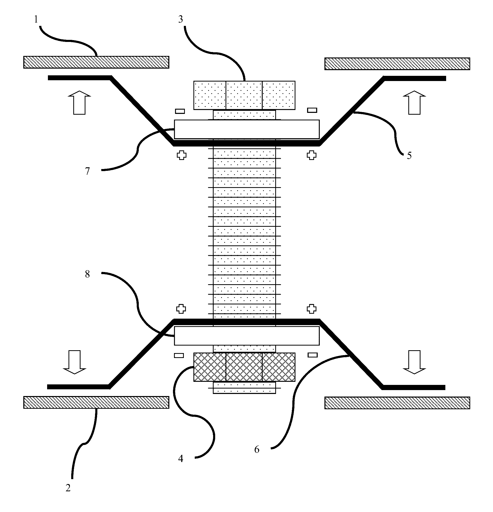
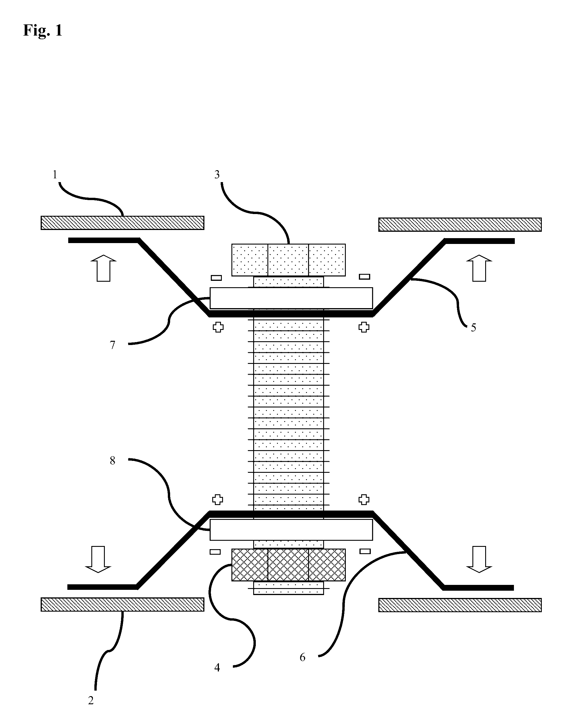
[0021]Referring now to the invention in more detail, in FIG. 1 there is shown an front view of a magnetic isolation mount composed of a mounting bracket 5 intended to secure one side of the mount assembly to a first member 1 and another mounting bracket 6 intended to secure another side of the mount assembly to the second member 2. The two mounting brackets 5,6 have magnets 7, 8 mounted through a connecting rod or bolt 3 ...


PUM


Abstract

The current invention is an improved magnetic vibration isolation mount and method that can provide a passive and active reduction in the actual and felt vibration transfer from one object to another. The vibration isolation mount is comprised of a mounting means for a first member, a mounting means for a second member, and a rod and magnetic field apparatus between the two mounts and members. The invention can also be seen as a method for the control of vibration transmission from a first member to a second member via either passive or active means.

Description

CROSS-REFERENCE TO RELATED APPLICATIONS[0001]Provisional Application No. 61 / 792,763 with Confirmation #9762STATEMENT REGARDING FEDERALLY SPONSORED RESEARCH OR DEVELOPMENT[0002]Not applicableREFERENCE TO SEQUENCE LISTING, A TABLE, OR A COMPUTER PROGRAM LISTING COMPACT DISK APPENDIX[0003]Not applicableBACKGROUND OF THE INVENTION[0004]The present invention is in the technical field of vibration dampening. More particularly, the present invention is in the technical field of magnetic fields that act to isolate vibration between two units. This invention relates to the improvement of a magnetic vibration isolating device and method.[0005]There is often a need to reduce the transmission of vibrational forces between two members of a structure or device while still maintaining sufficient mechanical support with the primary goal of reducing both vibration and noise felt by equipment and persons.[0006]There are many areas that have a need for the reduction in the transfer of vibrational forc...

Claims


Application Information

Patent Timeline
Patent Type & Authority Patents(United States)
IPC IPC(8): F16F15/03F16F6/00
CPCF16F15/03F16F6/00
Inventor SMITH, KYLE
Owner SMITH KYLE
Why Eureka
Try Eureka