Vibrating tray for diverted card inserts

a technology for removing and transferring cards, applied in the field of error handling, can solve the problem that the defective card cannot be attached to the sheet, and achieve the effect of reducing vibration transfer

Inactive Publication Date: 2016-12-06
PITNEY BOWES INC
View PDF5 Cites 0 Cited by
  • Summary
  • Abstract
  • Description
  • Claims
  • Application Information

AI Technical Summary

Benefits of technology

[0013]In another preferred embodiment, the tray is connected to the card attaching system with a vibration isolation mounting to minimize vibration transfer to the card attaching system.

Problems solved by technology

When a card rejection condition is detected, a defective card cannot be attached to the sheet.

Method used


Image

  • Vibrating tray for diverted card inserts
  • Vibrating tray for diverted card inserts
  • Vibrating tray for diverted card inserts

Examples


Embodiment Construction

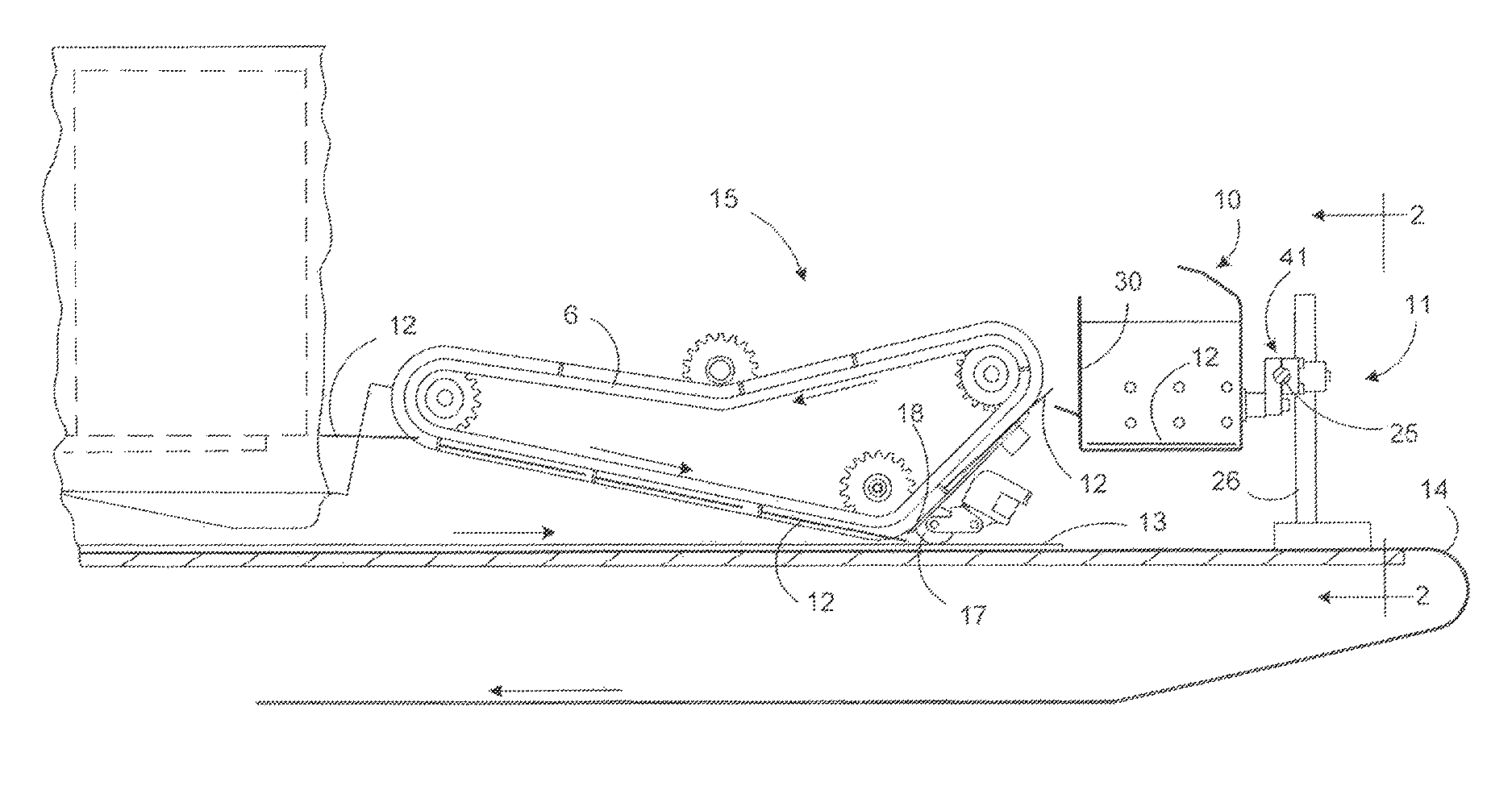
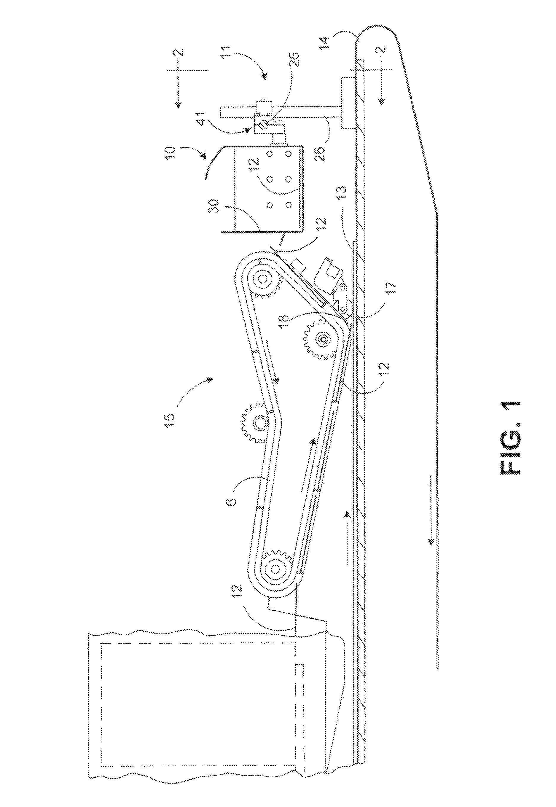
[0019]FIG. 1 shows the card attaching system in which the diverter collection tray operates. A card depositing feeder 15 receives cards 12 that are individually placed on sheets 13 that are transported on a transport belt 14. The paper sheets 13 will typically have an adhesive material placed on them at the position where the cards are to be attached. A feeder belt 6 in the feeder 15 moves the cards 12 through the feeder 15 mechanism. The cards 12 are released from the feeder 15 and they can be pressed into position on the sheet 13 by a roller 17.

[0020]In some cases, it will be determined that a card 12 cannot be placed on a sheet 13, and a diverter mechanism 18 will move to change the path of a rejected card 12 away from the feeder 15 opening, in an upward direction to a diverted card collection tray 10. Typical reasons for diverting a card may be that the card is damaged, the card is unreadable, the card is not the expected card for the particular mail piece that is being prepared...


PUM

PropertyMeasurementUnit
vertical displacementaaaaaaaaaa
perimeteraaaaaaaaaa
of rotationaaaaaaaaaa

Abstract

An automated apparatus and method for collecting and dispensing rejected cards in a tray in a card attaching system. Sheets are transported on a moving belt. Cards are fed from a feeder above the moving belt. Cards are deposited onto the sheets. When a card rejection condition is detected, a rejected card is diverted and deposited in a tray having a sloped chute. The sloped chute extends down to a lower position beyond an outside edge of the moving belt. To facilitate movement down the chute, the tray is vibrated. This vibration is accomplished by supporting the tray on a roller assembly that rolls on a surface of the moving belt as it passes under the sloped chute. The roller is non-circular or of an eccentric configuration, such that the axis of the roller will experience a vertical displacement as the roller rotates, jogging the tray.

Description

TECHNICAL FIELD[0001]The present invention relates to error handling in an automated system for attachment of plastic cards to mail items in a mail production machine.BACKGROUND OF THE INVENTION[0002]A mail insertion system or a “mailpiece inserter” is commonly employed for producing mailpieces intended for mass mail communications. Such mailpiece inserters are typically used by organizations such as banks, insurance companies and utility companies for producing a large volume of specific mail communications where the contents of each mailpiece are directed to a particular addressee.[0003]In many respects, a typical inserter resembles a manufacturing assembly line. Sheets and other raw materials (i.e., a web of paper stock, enclosures, and envelopes) enter the inserter system as inputs. Various modules or workstations in the inserter system work cooperatively to process the sheets until a finished mail piece is produced. The precise configuration of each inserter system depends upon...

Claims


Application Information

Patent Timeline
Patent Type & Authority Patents(United States)
IPC IPC(8): B65H39/10B65H29/52B65G27/04B65H29/62B65G27/18B65G27/08B07C5/36B65H39/06
CPCB65G27/04B07C5/36B65G27/08B65G27/18B65H29/52B65H29/62B65H39/06B65H2301/441B65H2301/4462B65H2404/6922B65H2404/731B65H2701/1914
Inventor DEFIGUEIREDO, CARLOS L.MASOTTA, JOHN R.
Owner PITNEY BOWES INC
Why Eureka
Try Eureka