
Nmr magnet system with stirling cooler

a technology of magnet system and cooler, which is applied in the field of nmr magnet system, can solve the problems of increasing the overall cost of operation, the inability of the nmr magnet system to operate, and the increase in the cost of helium required for cooling the magnet to temperatures suitable for superconductivity, so as to achieve the effect of minimal effect on nmr measurements and low overall cost of ownership

Active Publication Date: 2022-09-15
BRUKER BIOSPIN
View PDF4 Cites 0 Cited by
  • Summary
  • Abstract
  • Description
  • Claims
  • Application Information

AI Technical Summary

Benefits of technology

The patent text describes a system for cooling an NMR magnet using a Stirling cooler. A Stirling cooler is a refrigerator that uses a special process to create a stable, low-temperature gas. This refrigeration technology can provide efficient and reliable cooling with little mechanical vibration. The system also includes a flexible thermally conductive tube that isolates the cooler from the cold shield, minimizing any transfer of vibration. Finally, a damper or an acceleration sensor can be used to further reduce mechanical vibrations. The technical effects of this system include improved cooling efficiency, reduced vibration, and improved measurement accuracy.

Problems solved by technology

Over time, they require periodic refilling with liquid cryogens by trained personnel, and during cryogenic transfer, the NMR magnet system cannot be operated due to instrument instability.
Furthermore, the cost of helium required for cooling the magnet to temperatures suitable for superconductivity tends to rise over time.
Beyond that, PTRs require regular servicing of their components by trained personnel, which increases the overall cost of operation significantly.

Method used


Image

  • Nmr magnet system with stirling cooler
  • Nmr magnet system with stirling cooler
  • Nmr magnet system with stirling cooler

Examples


Embodiment Construction

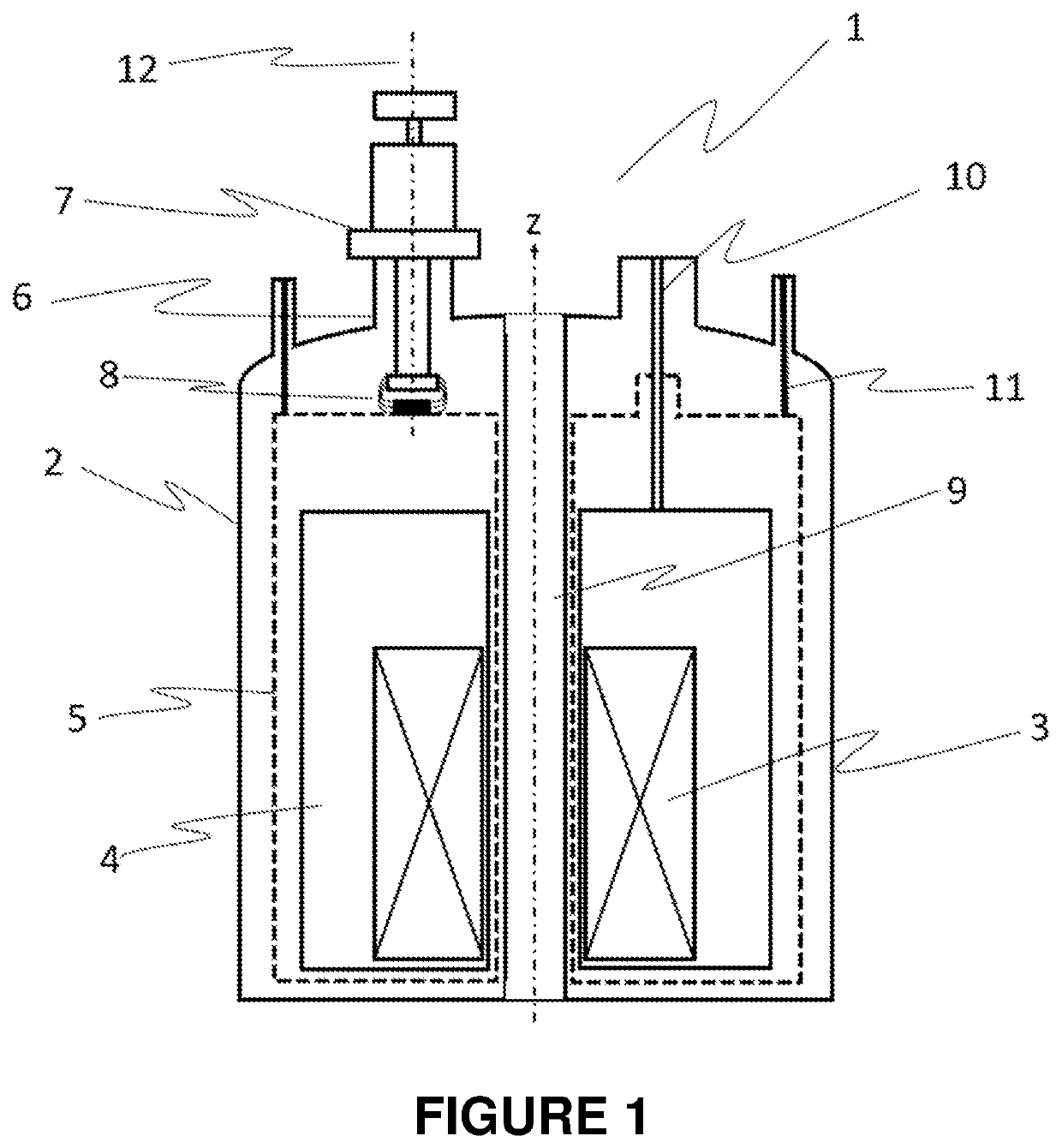
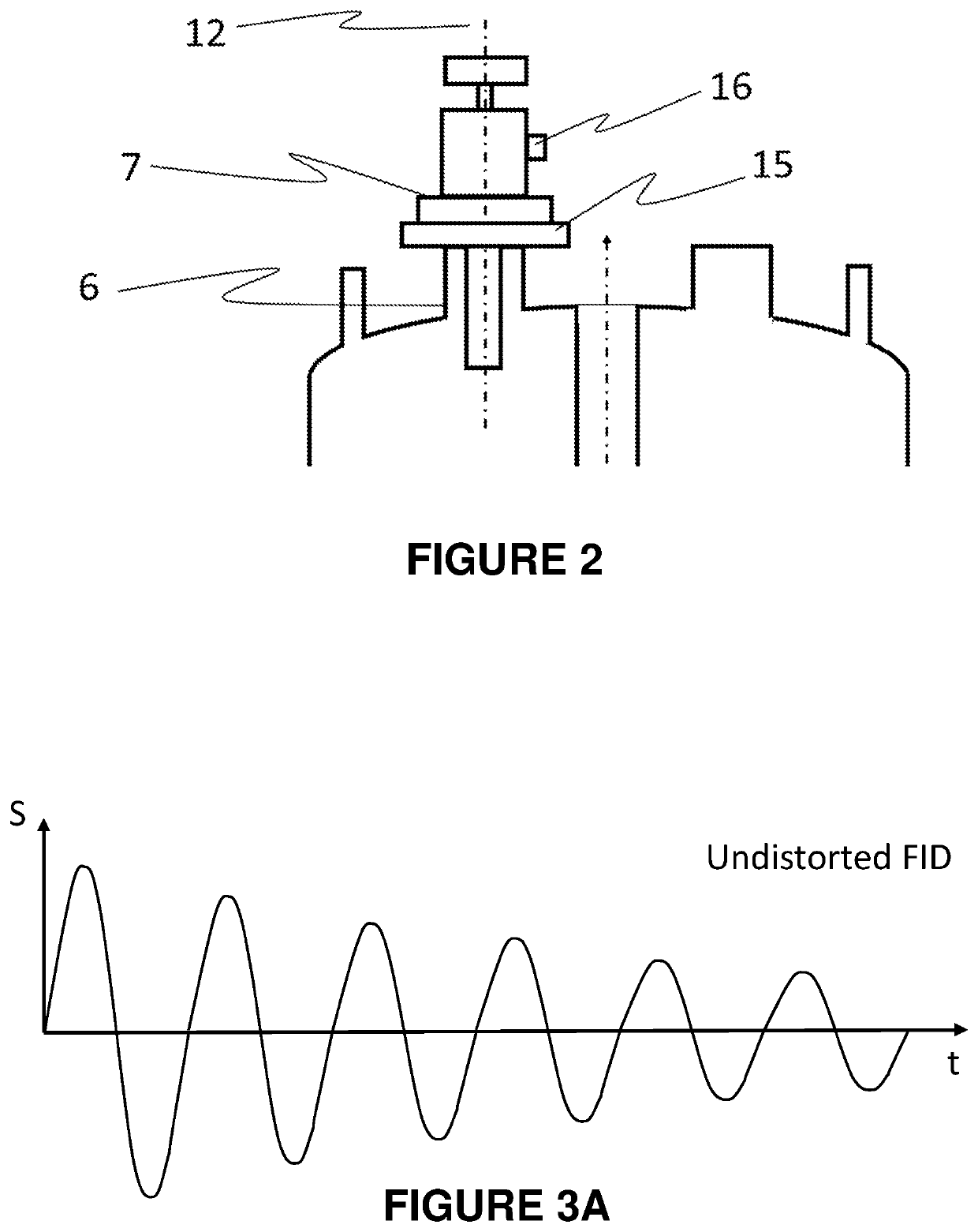
[0022]FIG. 1 shows an NMR magnet system 1 with a Stirling cooler 7. The NMR magnet system comprises a housing 2, and a magnet coil 3 in a helium vessel 4. The helium vessel is surrounded by a cold shield 5, which is fixed to the housing by holding rods 11. The helium vessel is connected to holding tube 10, which may be one of several holding tubes, and which provides a passage through which helium gas within the helium vessel 4 may pass to an external collection chamber (not shown). Holding tubes 10 are also used for connecting magnet coil 3 to an external power supply for charging the magnet, and for refilling helium in the helium vessel 4. Furthermore, they provide structural support for the helium vessel 4, helping to hold it in place relative to the housing 2. The Stirling cooler 7 is attached to a neck tube 6 of the NMR magnet system. Thermal contact between the cold shield 5 and the neck tube 6 is provided by thermal coupling 8, which also provides mechanical isolation of the ...


PUM


Abstract

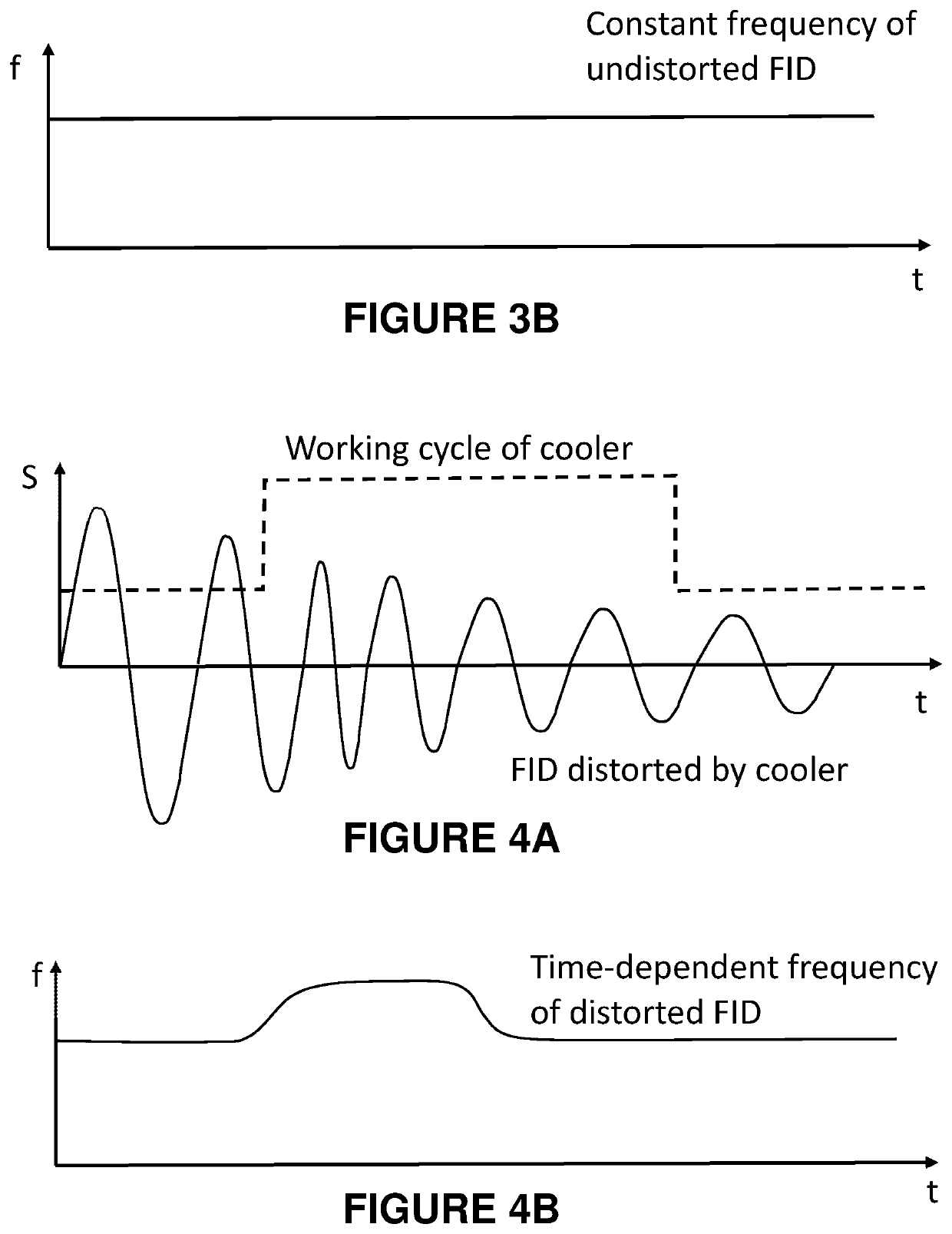
An NMR magnet system uses a Stirling cooler having a cold head that extends into a housing of the system to cool a cold shield surrounding a cryogen vessel. The system may have a damper located between the cooler and the cold shield to reduce a transmission of vibration from the cooler to a magnet coil immersed in the cryogen. The damper may be passive, or may be part of an active damping system that uses an acceleration sensor to drive an active damper that compensates for cooler vibration. A compensation apparatus may use a stored characteristic of a signal distortion caused by the vibration and, in response to a trigger signal from the cooler, apply compensation to an excitation signal provided to a sample by an NMR probe in a bore of the magnet coil, or to an FID signal from the sample that is detected by the probe.

Description

BACKGROUND OF THE INVENTIONField of the Invention[0001]This invention relates generally to the field of NMR magnet systems and, more specifically, to the use of active cooling with such systems.Description of the Related Art[0002]Nuclear magnetic resonance (NMR) magnet systems are an essential tool for biomolecular scientists. Over time, they require periodic refilling with liquid cryogens by trained personnel, and during cryogenic transfer, the NMR magnet system cannot be operated due to instrument instability. Furthermore, the cost of helium required for cooling the magnet to temperatures suitable for superconductivity tends to rise over time. To partly overcome the depletion of helium in such systems, so-called two-stage pulse tube refrigerators (PTR) have been used in recent years. A first stage is connected to a cold shield of the NMR magnet system, while a second stage with a lower temperature is thermally coupled via helium vapor to the helium vessel of the NMR magnet. PTRs p...

Claims


Application Information

Patent Timeline
Patent Type & Authority Applications(United States)
IPC IPC(8): G01R33/34G01R33/46
CPCG01R33/3403G01R33/34007G01R33/46G01R33/3815G01R33/3804G01R33/4625F25B9/14G01R33/28F25B2500/13
Inventor LAUKIEN, FRANKDECKER, FRANK
Owner BRUKER BIOSPIN
Learn More