Method and apparatus for a high resolution imaging system

a high-resolution imaging and high-resolution technology, applied in the manufacture of electrode systems, electric discharge tubes/lamps, instruments, etc., can solve the problem of replacing that takes less than a day to perform, and achieve the effect of economic and cost-effectiv

Active Publication Date: 2017-01-31
FUTRFAB
View PDF16 Cites 8 Cited by
  • Summary
  • Abstract
  • Description
  • Claims
  • Application Information

AI Technical Summary

Benefits of technology

[0013]In some embodiments, the methods of producing products in the mentioned cleanspace fabricator may be useful to produce small amounts of a product. An imaging system comprised of a multitude of individual imaging elements may define a lithography option for a low volume fabricator that is both economical and cost effective in that expenses such as the production of lithography masks may not be required in some embodiments. In some cases the fabricator environment may be useful in creating and producing imaging system components as well.

Problems solved by technology

The use of the tool chassis together with a toolPod may result in a replacement that takes less than a day to perform.

Method used


Image

  • Method and apparatus for a high resolution imaging system
  • Method and apparatus for a high resolution imaging system
  • Method and apparatus for a high resolution imaging system

Examples


Embodiment Construction

[0051]In patent disclosures by the same inventive entity, the innovation of the cleanspace fabricator has been described. In place of a cleanroom, fabricators of this type may be constructed with a cleanspace that contains the wafers, typically in containers, and the automation to move the wafers and containers around between ports of tools. The cleanspace may typically be much smaller than the space a typical cleanroom may occupy and may also be envisioned as being turned on its side. In some embodiments, the processing tools may be shrunk which changes the processing environment further.

Description of a Linear, Vertical Cleanspace Fabricator

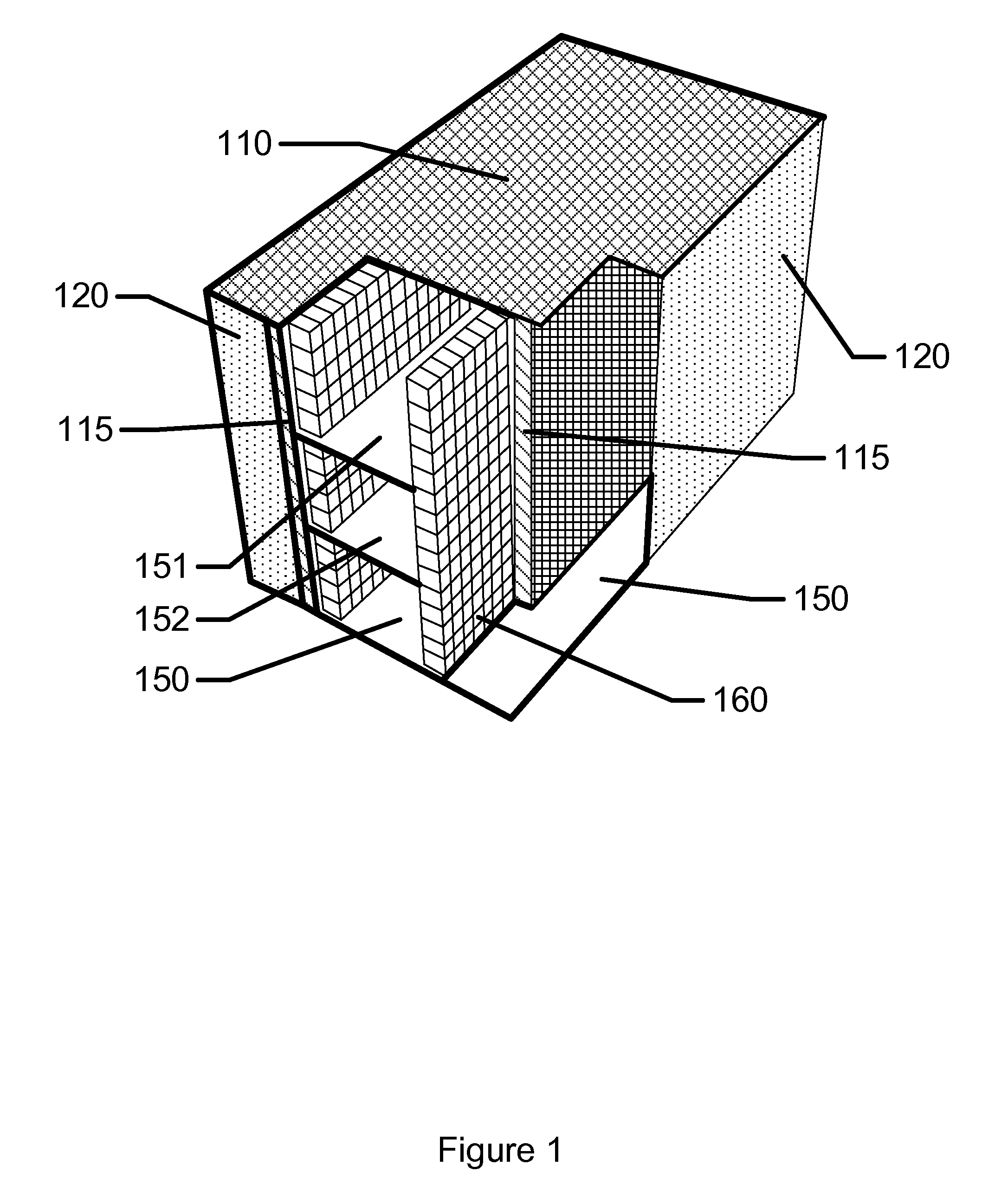
[0052]There are a number of types of cleanspace fabricators that may be possible with different orientations. For the purposes of illustration, one exemplary embodiment includes an implementation with a fab shape that is planar with tools oriented in vertical orientations. An exemplary representation of what the internal structure of these type...


PUM

PropertyMeasurementUnit
radiusaaaaaaaaaa
bias potentialaaaaaaaaaa

Abstract

The present invention provides apparatus for an imaging system comprising a multitude of imaging elements upon a substrate. In some embodiments the substrate may be approximately round with a radius of approximately one inch. Various methods relating to using and producing an imaging system are discussed.

Description

CROSS REFERENCE TO RELATED APPLICATIONS[0001]This application is a continuation in part of the Utility application Ser. No. 14 / 594,335, filed Jan. 12, 2015 and entitled: “METHOD AND APPARATUS FOR AN IMAGING SYSTEM.” The application Ser. No. 14 / 594,335 in turn claims the benefit of the U.S. Provisional application bearing the Ser. No. 61 / 926,471, filed Jan. 13, 2014 and entitled METHOD AND APPARATUS FOR AN IMAGING SYSTEM. The contents of each are relied upon and hereby incorporated by reference.FIELD OF THE INVENTION[0002]The present invention relates to methods and associated apparatus and methods which relate to processing tools used to create imaged layers on substrates. Massively parallel implements of electron beam or chemical species beam imaging elements may be combined to form a full substrate processing system. In some embodiments the imaging systems may be used in conjunction with cleanspace fabricators. The present invention may also relate to methods and apparatus to capi...

Claims


Application Information

Patent Timeline
Patent Type & Authority Patents(United States)
IPC IPC(8): H01J37/317H01J37/248H01J37/20B82B3/00H01J37/06H01J37/08H01J9/02
CPCH01J37/317B82B3/00H01J9/022H01J37/06H01J37/08H01J37/20H01J37/248H01J37/3177H01J2237/1205H01J2237/20H01J2237/303H01J2237/304H01J2237/3174H01J2237/31759H01J2237/31798Y10T29/49004G03F9/00H01J37/244
Inventor FLITSCH, FREDERICK A.
Owner FUTRFAB
Why Eureka
Try Eureka