Power converter

a technology of power converter and converter plate, which is applied in the direction of power conversion system, dc-dc conversion, instruments, etc., can solve the problem of increasing cost, and achieve the effect of suppressing the fluctuation of detection accuracy and reducing cos

Active Publication Date: 2017-01-31
TOYOTA JIDOSHA KK
View PDF5 Cites 0 Cited by
  • Summary
  • Abstract
  • Description
  • Claims
  • Application Information

AI Technical Summary

Benefits of technology

[0007]In view of the above, a power converter that can suppress cost increase and fluctuation in detection accuracy is provided.
[0009]According to the one aspect, since the voltage of the first port and the voltage of the third port are detected by the common detection circuit, cost can be reduced and the fluctuation in the detection accuracy can be suppressed.

Problems solved by technology

However, when such a configuration in which separate detection circuits are used to detect the voltage of the first port and the voltage of the third port is adopted, cost tends to be increased.

Method used


Image

  • Power converter
  • Power converter
  • Power converter

Examples


Embodiment Construction

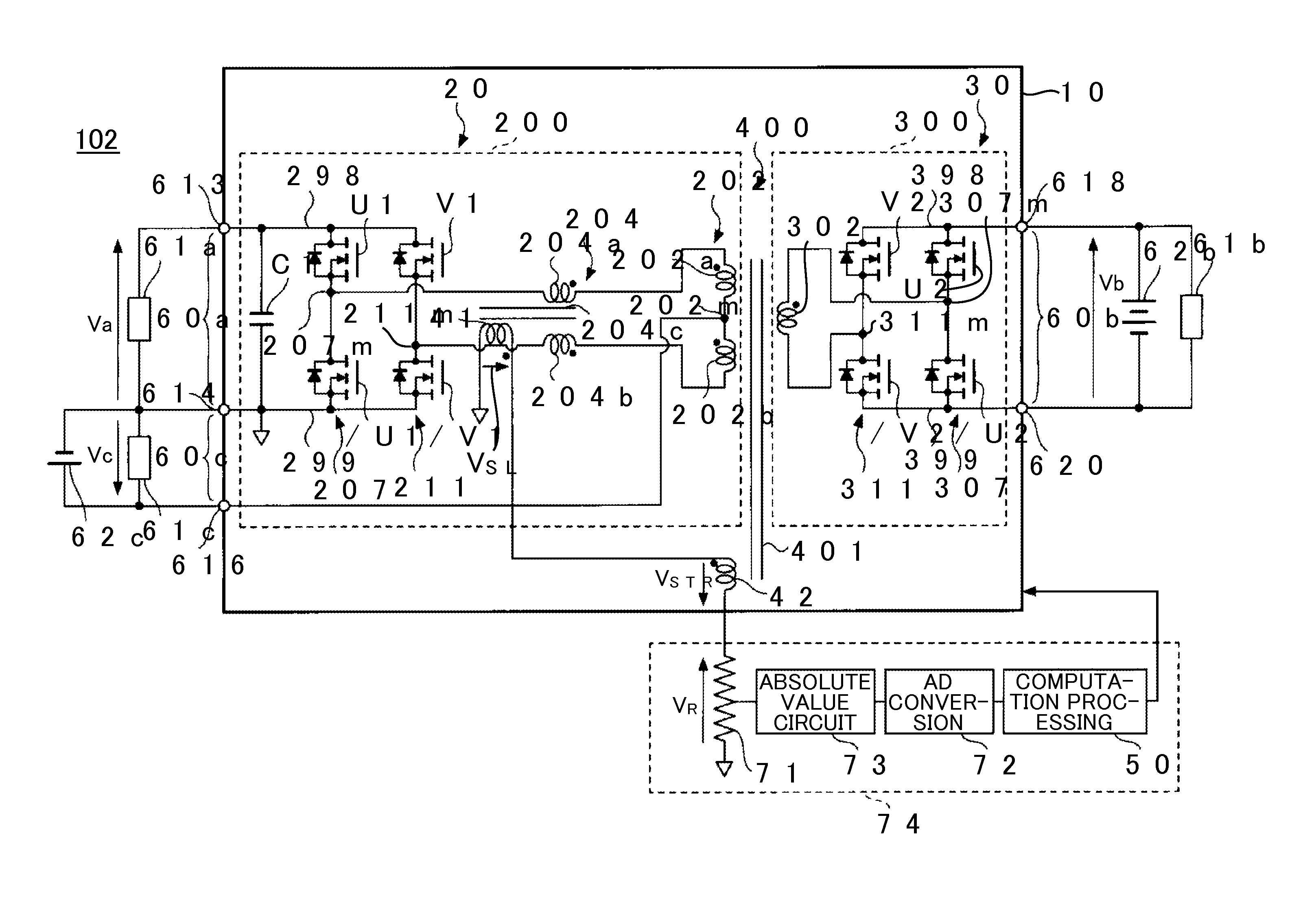
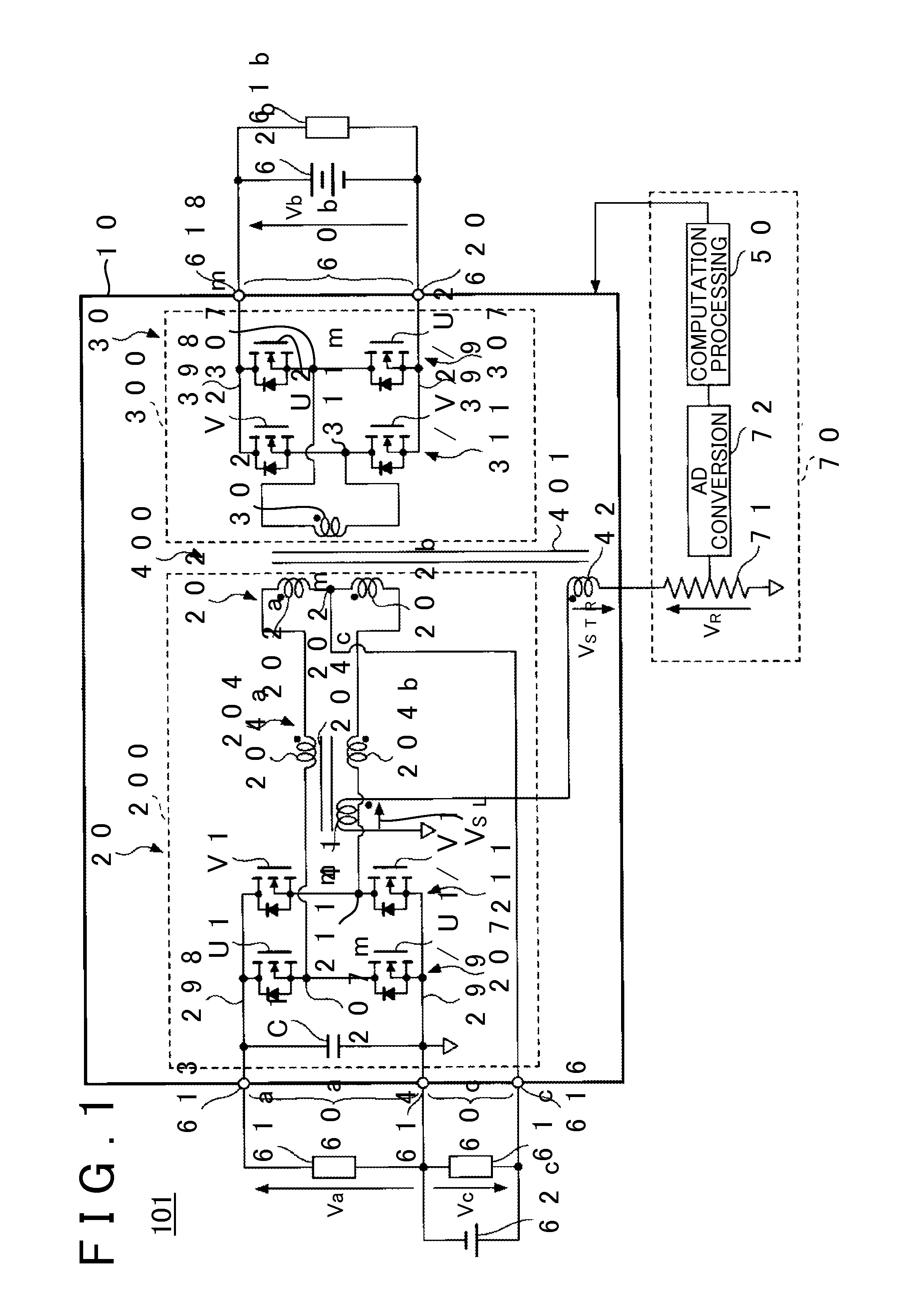
[0016]101>FIG. 1 is a view that shows one example of a configuration of a power supply device 101 as one embodiment of the power converter. The power supply device 101 is a power supply system that includes, for example, a power supply circuit 10 and a detection circuit 70. The power supply device 101 is a system that is mounted in a vehicle, such as an automobile, and supplies electric power to each onboard load, for example.

[0017]The power supply device 101 has, as a primary-side port, a first port 60a, to which a primary-side high-voltage system load 61a is connected, and a second port 60c, to which a primary-side low-voltage system load 61c and an auxiliary battery 62c are connected, for example. The auxiliary battery 62c is one example of a primary-side low-voltage system power supply for supplying the electric power to the primary-side low-voltage system load 61c that is operated by the same voltage system (for example, a 12 V system) as the auxiliary battery 62c. In addition,...


PUM


Abstract

A power converter including: a transformer; a primary-side full-bridge circuit including a primary-side coil of the transformer and a magnetically-coupled reactor, in which two reactors connected to both ends of the primary-side coil are magnetically coupled; a first port connected to a positive electrode bus bar of the primary-side full-bridge circuit; a second port connected to a tap of the primary-side coil; a secondary-side full-bridge circuit including a secondary-side coil of the transformer; a third port connected to a positive electrode bus bar of the secondary-side full-bridge circuit; a first search coil wound around a core of the magnetically-coupled reactor; a second search coil wound around a core of the transformer; and a detection circuit detecting voltages of the first port and the third port by measuring a variation in a sense voltage generated by combining voltages of the first search coil and the second search coil.

Description

INCORPORATION BY REFERENCE[0001]The disclosure of Japanese Patent Application No. 2014-239036 filed on Nov. 26, 2014 including the specification, drawings and abstract is incorporated herein by reference in its entirety.BACKGROUND OF THE INVENTION[0002]1. Field of the Invention[0003]The invention relates to a technique of converting electric power among plural ports.[0004]2. Description of Related Art[0005]A power converter that includes: a transformer; a primary-side full-bridge circuit that is provided on a primary side of the transformer; a secondary-side full-bridge circuit that is provided on a secondary side of the transformer; a first port that is connected to a positive electrode bus bar of the primary-side full-bridge circuit; a second port that is connected to a tap of a primary-side coil of the transformer; and a third port that is connected to a positive electrode bus bar of the secondary-side full-bridge circuit has been known (for example, see Japanese Patent Applicati...

Claims


Application Information

Patent Timeline
Patent Type & Authority Patents(United States)
IPC IPC(8): H02M3/335H02M7/5387
CPCH02M3/33584H02M3/33561
Inventor USAMI, TOMOHIRO
Owner TOYOTA JIDOSHA KK
Why Eureka
Try Eureka