Process for the detection of optical signals

a technology for optical signals and processing methods, applied in the direction of electroluminescent light sources, electroluminescent transceivers, electric lighting sources, etc., can solve the problems of increased overall size of prior-art light modules, additional detectors, and additional space, and achieve low cost, low design effort, and cost-effective and simple manner

Active Publication Date: 2017-01-31
DRAGERWERK AG
View PDF18 Cites 2 Cited by
  • Summary
  • Abstract
  • Description
  • Claims
  • Application Information

AI Technical Summary

Benefits of technology

[0005]An object of the present invention is to eliminate the above-described drawbacks at least partially. An object of the present invention is, in particular, to make available a process for the detection of optical signals with a light module, such a light module for the detection of optical signals as well as the use of a light module for a lighting fixture for an operating room, which make it possible to perform a preferably continuous detection over time at low costs and with a low design effort in a cost-effective and simple manner.

Problems solved by technology

The drawback of prior-art processes and prior-art light modules is that the detection must be carried out by additional components in the form of additional detectors.
These require additional space for their installation, as a result of which the overall size of prior-art light modules is increased.
In addition, additional components in the form of detectors lead to additional costs and additional expenses for materials.
Another drawback arises because the additional detectors do not have exactly the same optical viewing direction, which may be especially disturbing in case of close objects.

Method used


Image

  • Process for the detection of optical signals
  • Process for the detection of optical signals
  • Process for the detection of optical signals

Examples


Embodiment Construction

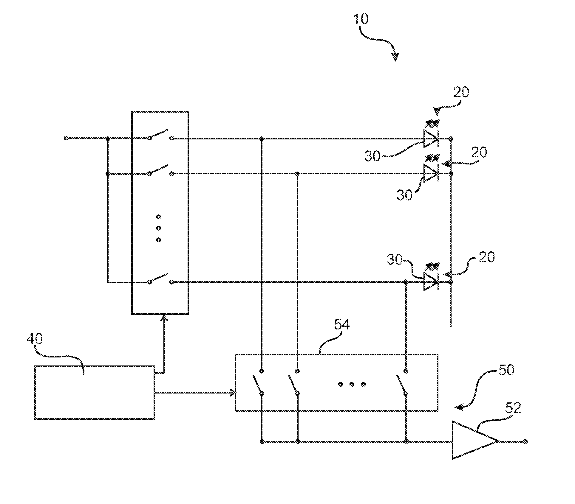
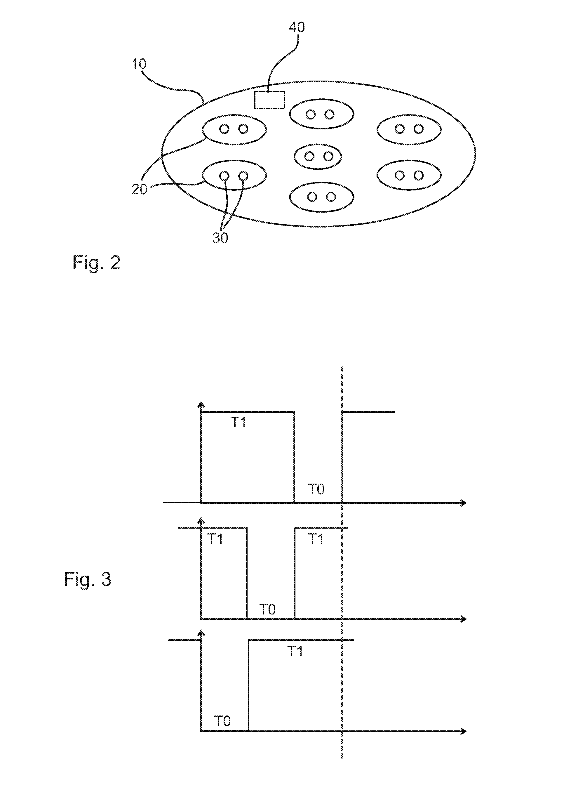
[0034]Referring to the drawings, FIG. 2 shows an embodiment of the light module 10 according to the present invention, which has a total of seven light sources 20. Each of these light sources 20 is provided with two LEDs 30 in this embodiment. At least two light sources 20 with at least one LED 30 each are provided as the minimum according to the present invention. Further, the embodiment according to FIG. 2 has a computer 40, which is designed especially to carry out a process according to the present invention. This computer 40 also performs the pulse width modulation of the individual LEDs 30 in order to control the light intensity of the light module 10.

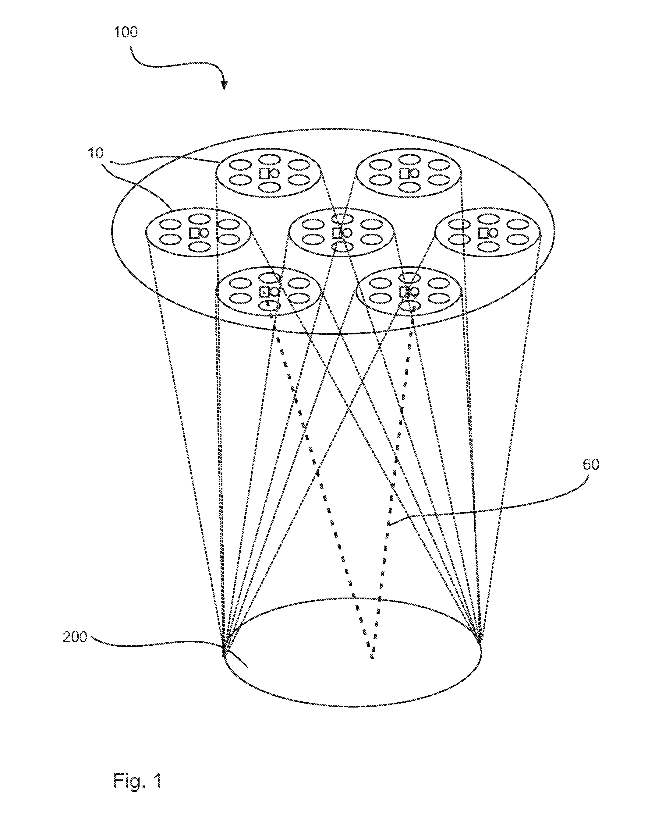
[0035]FIG. 1 shows an illuminating device 100 as it can be used, for example, as a lighting fixture for an operating room. A total of seven light modules 10, which may be designed especially according to FIG. 2, are provided in this embodiment. All light modules 10 illuminate an illuminated area 200 together and overlappingly. Th...


PUM


Abstract

A process for the detection of optical signals with a light module (10) with at least two light sources (20) operated with on / off times with at least one LED (30). The process includes the steps of operating the at least two light sources (20) with time-shifted on / off times and detecting optical signals with the light source (20) that occurs in the off time at the given time.

Description

CROSS REFERENCE TO RELATED APPLICATIONS[0001]This application is a United States National Phase application of International Application PCT / EP2013 / 064344 filed Jul. 8, 2013 and claims the benefit of priority under 35 U.S.C. §119 of German Patent Application DE 10 2012 014 715.5 filed Jul. 25, 2012, the entire contents of which are incorporated herein by reference.FIELD OF THE INVENTION[0002]The present invention pertains to a process for the detection of optical signals with a light module, a light module for the detection of optical signals, as well as to the use of such a light module for a lighting fixture for an operating room.BACKGROUND OF THE INVENTION[0003]Processes for the detection of optical signals are basically known. For example, light modules of illuminating devices have additional detectors in order to detect optical signals. For example, a feedback concerning a reflected amplitude from such a detector can be recognized. If an illumination area is defined for an illu...

Claims


Application Information

Patent Timeline
Patent Type & Authority Patents(United States)
IPC IPC(8): H04B10/43H04B10/60H05B33/08H05B37/02H05B44/00
CPCH04B10/60H05B33/083H05B33/0827H05B33/0854H05B37/0272H05B37/0281H05B45/44H05B47/16H05B45/12H05B45/46H05B45/48
Inventor SATTLER, FRANK
Owner DRAGERWERK AG
Why Eureka
Try Eureka