
Noise level based exposure time control for sequential subimages

a sub-image and noise level technology, applied in the field of scene imaging, can solve the problems of affecting the overall image, and affecting the overall image, and achieve the effect of compensating for the overall imag

Active Publication Date: 2017-01-31
SONY CORP
View PDF7 Cites 1 Cited by
  • Summary
  • Abstract
  • Description
  • Claims
  • Application Information

AI Technical Summary

Benefits of technology

This approach dynamically controls exposure times and compensates for motion, reducing blurring and ghosting, thereby efficiently capturing high dynamic range images with improved resolution and range compared to traditional methods.

Problems solved by technology

However, due to the time offset between capturing the different images, the combined HDR image may suffer from blurring or ghosting of moving objects in the imaged scene and / or from overall blurring due to movement of the imaging sensor while capturing the different images.
While such undesirable effects may in principle be reduced by decreasing the time offset between capturing the different images, such decrease of the time offset may often be limited by the utilized imaging sensor and associated image processing electronics.
For example, detecting the outputs of all pixels of the imaging sensor and processing these outputs to obtain the desired image data may limit the time offset.

Method used


Image

  • Noise level based exposure time control for sequential subimages
  • Noise level based exposure time control for sequential subimages
  • Noise level based exposure time control for sequential subimages

Examples


Embodiment Construction

[0024]In the following, exemplary embodiments of the invention will be described in more detail. It has to be understood that the following description is given only for the purpose of illustrating the principles of the invention and is not to be taken in a limiting sense. Rather, the scope of the invention is defined only by the appended claims and is not intended to be limited by the exemplary embodiments described hereinafter.

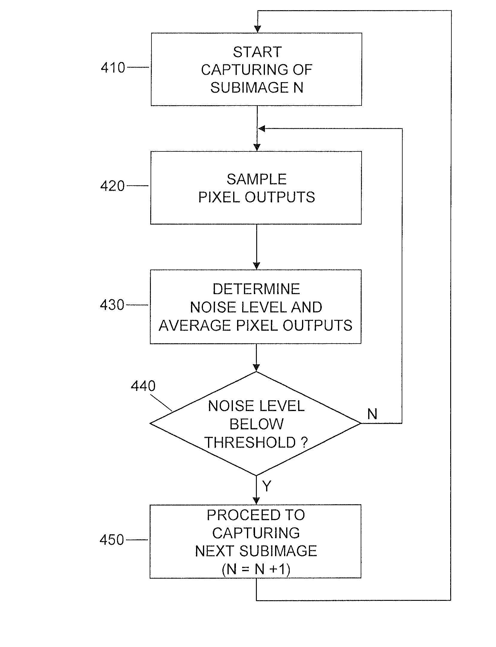
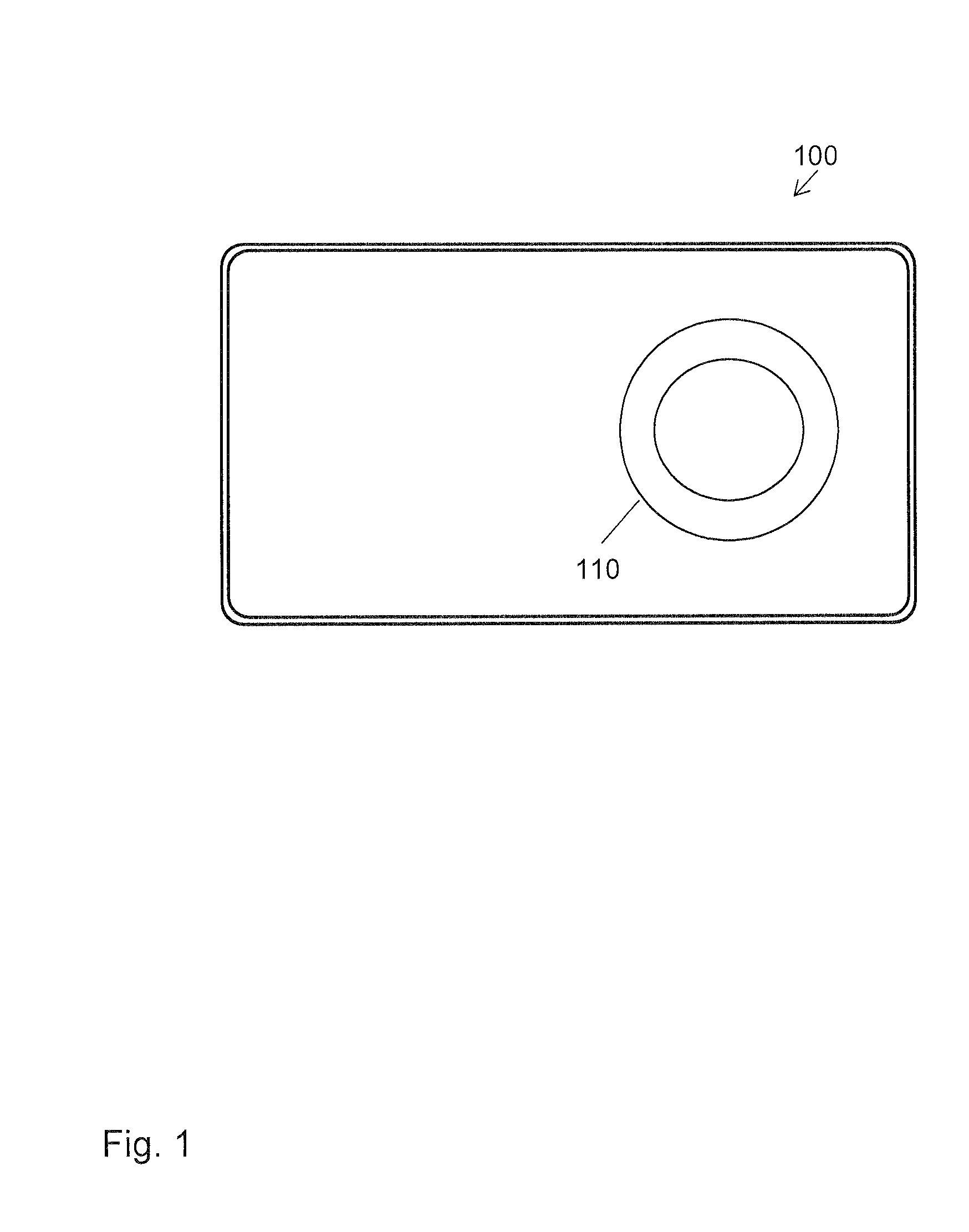
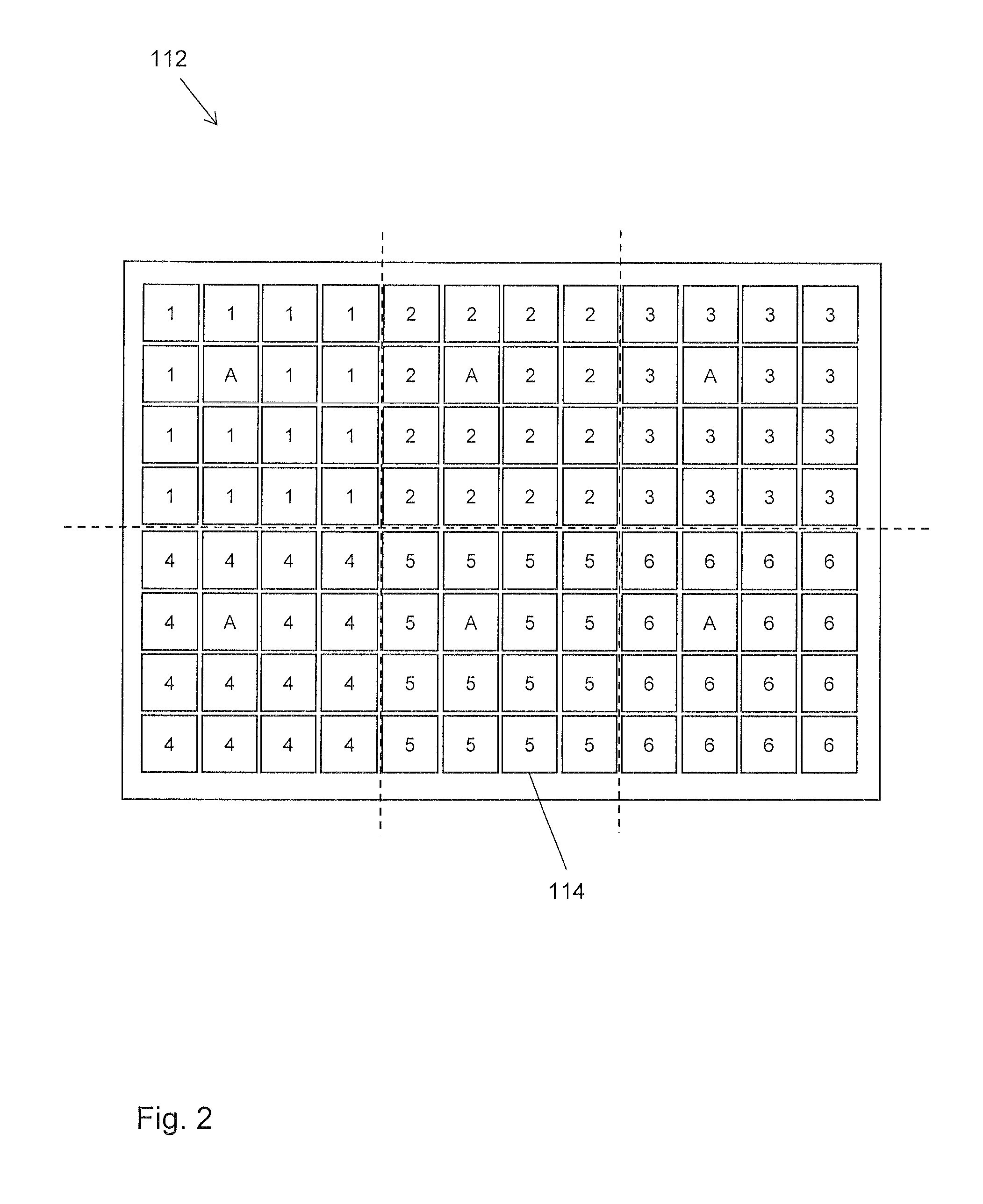
[0025]The illustrated embodiments relate to imaging of a scene, specifically with the aim of efficiently capturing HDR still images or HDR videos. In the illustrated embodiments, this involves utilization of an imaging sensor which is organized in multiple subsets of pixels. The subsets of pixels are utilized for capturing a sequence of subimages. In this process, each subset captures a corresponding one of the subimages. For capturing each subimage, an exposure time is individually controlled. This is accomplished depending on a noise level detected in the ...


PUM


Abstract

A sequence of multiple subimages is captured by an imaging sensor organized in multiple subsets of pixels. Each of the subsets of pixels is assigned to capturing a corresponding one of the subimages. For each of the subsets of pixels, a noise level of an output of the pixels of the subset is measured. Depending on the measured noise level, an exposure time for capturing the corresponding subimage is controlled.

Description

FIELD OF THE INVENTION[0001]The present invention relates to a method of imaging a scene and to a correspondingly configured device.BACKGROUND OF THE INVENTION[0002]Various kinds of electronic devices, e.g., smartphones, tablet computers, or digital cameras, may be equipped with increasingly sophisticated imaging functionalities. Such imaging functionalities for example include capturing of high dynamic range (HDR) still images or videos. Here, the term “HDR” means that a dynamic range concerning an ability to resolve features in regions of low luminosity and high luminosity of an imaged scene is increased as compared to conventionally captured images. This means that a certain contrast level allowing for resolving image details may be attained both in image regions of low luminosity and image regions of high luminosity, avoiding contrast limiting effects of under exposure or over exposure.[0003]A typical way of capturing HDR images is to utilize an imaging sensor for capturing mult...

Claims


Application Information

Patent Timeline
Patent Type & Authority Patents(United States)
IPC IPC(8): H04N5/225H04N5/345H04N5/232H04N5/357H04N5/235
CPCH04N5/2355H04N5/2353H04N5/23232H04N5/23254H04N5/23258H04N5/23264H04N5/345H04N5/357H04N23/741H04N25/44H04N25/60H04N23/73H04N23/682H04N23/951H04N23/6811H04N23/6812
Inventor THORN, OLAGUSTAVSSON, JONAS
Owner SONY CORP
Learn More