
Image-capturing apparatus, image processing system, image processing method, and program

a technology of image processing system and image, applied in the field of image capture apparatus, image processing system, image processing method, and program, can solve problems such as accumulation of observation nois

Pending Publication Date: 2022-11-17
SONY CORP
View PDF0 Cites 1 Cited by
  • Summary
  • Abstract
  • Description
  • Claims
  • Application Information

AI Technical Summary

Benefits of technology

The technology described in this patent text, called visual inertial odometry, uses a short exposure time to prevent blurred images from being detected due to camera movement. However, if there are a lot of moving objects in the image, the estimation accuracy of the object's location and pose may be reduced. To address this problem, the patent suggests using a longer exposure time to capture more detail in the image and improve the accuracy of self-location and pose estimation.

Problems solved by technology

However, in a system that primarily uses an IMU in order to estimate a self-location and a pose of an object using SLAM, observation noise is accumulated in process of performing integration processing on an acceleration and an angular velocity that are detected by the IMU, and the reliability of sensor data that is output by the IMU is ensured only for a short period of time.
This may result in being unpractical.

Method used


Image

  • Image-capturing apparatus, image processing system, image processing method, and program
  • Image-capturing apparatus, image processing system, image processing method, and program
  • Image-capturing apparatus, image processing system, image processing method, and program

Examples


first configuration example

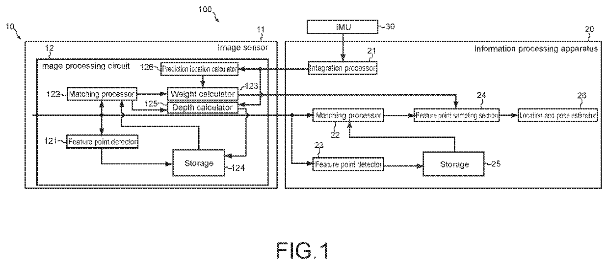
[0030]FIG. 1 is a block diagram illustrating an example of a configuration of an image processing system 100 according to the present embodiment. The image processing system 100 includes an image-capturing apparatus 10, an information processing apparatus 20, and an IMU 30.

[0031](Image-Capturing Apparatus)

[0032]As illustrated in FIG. 1, the image-capturing apparatus 10 includes an image sensor 11. The image-capturing apparatus 10 captures an image of a real space using the image sensor 11 and various members such as a lens used to control the formation of an image of a subject on the image sensor 11, and generates a captured image.

[0033]The image-capturing apparatus 10 may capture a still image at a specified frame rate, or may capture a moving image at a specified frame rate. The image-capturing apparatus 10 can capture an image of a real space at a specified frame rate (for example, 240 fps). In the following description, an image captured at a specified frame rate (for example, 2...

second configuration example

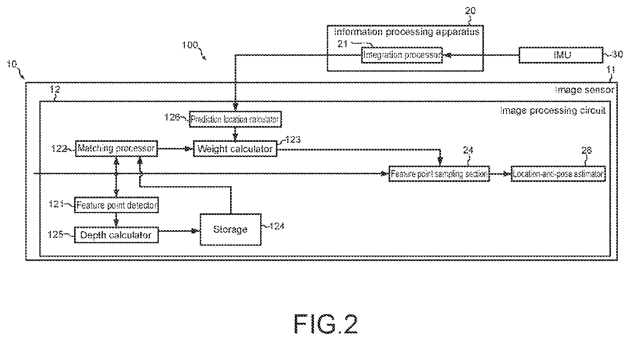
[0060]FIG. 2 is a block diagram illustrating another example of the configuration of the image processing system 100 according to the present embodiment. As illustrated in FIG. 2, the image processing system 100 may have a configuration in which the image processing circuit 12 includes the feature point sampling section 24 and the location-and-pose estimator 26. Note that, in a second configuration example, a structural element that is similar to the structural element in the first configuration example is denoted by a reference numeral similar to the reference numeral used in the first configuration example, and a description thereof is omitted.

third configuration example

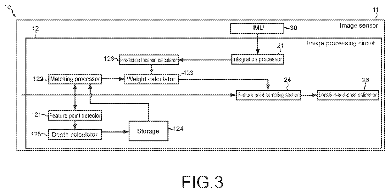
[0061]FIG. 3 is a block diagram illustrating another example of a configuration of the image-capturing apparatus 10 according to the present embodiment. As illustrated in FIG. 3, the image-capturing apparatus 10 of the present technology may include the IMU 30 and the image processing circuit 12, and may have a configuration in which the image processing circuit 12 includes the integration processor 21, the feature point sampling section 24, and the location-and-pose estimator 26. Note that, in a third configuration example, a structural element that is similar to the structural element in the first configuration example is denoted by a reference numeral similar to the reference numeral used in the first configuration example, and a description thereof is omitted.

[0062]The examples of the configuration of the image processing system 100 have been described above. Each of the structural elements described above may be configured using a general-purpose member, or using hardware speci...


PUM


Abstract

To provide an image-capturing apparatus, an image processing system, an image processing method, and a program that make it possible to prevent a moving object from being detected in image information. An image-capturing apparatus according to the present technology includes an image processing circuit. The image processing circuit detects feature points for respective images of a plurality of images captured at a specified frame rate, and performs processing of calculating a moving-object weight of the detected feature point a plurality of times.

Description

TECHNICAL FIELD[0001]The present technology relates to an image-capturing apparatus, an image processing system, an image processing method, and a program.BACKGROUND ART[0002]Simultaneous localization and mapping (SLAM) that estimates a self-location and creates an environment map at the same time is adopted as a technology that estimates a self-location and a pose of, for example, a camera or an autonomous vacuum cleaner (for example, Patent Literature 1), and a method using an inertial measurement unit (IMU) is often proposed. However, in a system that primarily uses an IMU in order to estimate a self-location and a pose of an object using SLAM, observation noise is accumulated in process of performing integration processing on an acceleration and an angular velocity that are detected by the IMU, and the reliability of sensor data that is output by the IMU is ensured only for a short period of time. This may result in being unpractical.[0003]Thus, a technology called visual inerti...

Claims


Application Information

Patent Timeline
Patent Type & Authority Applications(United States)
IPC IPC(8): G06T7/246G06V10/25G06T7/73
CPCG06T7/246G06V10/25G06T7/73H04N23/60G06V30/18143G06T7/248
Inventor KAWASHIMA, MANABU
Owner SONY CORP
Learn More