
Positive photoresist compositions having enhanced processing time

a technology of photoresist and composition, applied in the field of positive photoresist compositions having enhanced processing time, can solve the problems of increased energy requirements, long processing time of positive photoresists, and problems in the finished product, and achieve the effect of shortening the tim

Inactive Publication Date: 2004-10-14
PPG IND OHIO INC
View PDF27 Cites 1 Cited by
  • Summary
  • Abstract
  • Description
  • Claims
  • Application Information

AI Technical Summary

Benefits of technology

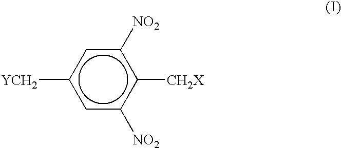
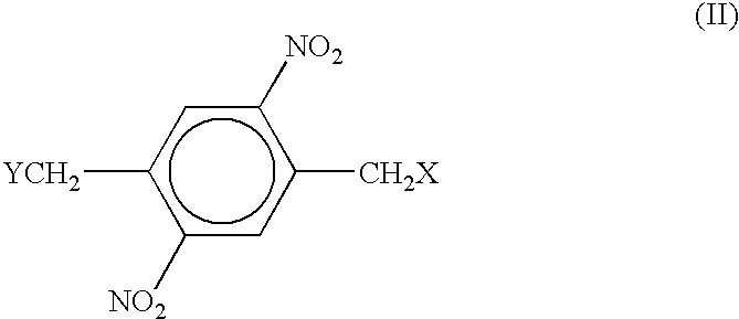
The present invention relates to photoresist compositions that have enhanced processing times. The addition of a photoacid generator, such as a diazide, to a dinitrobenzyl compound results in faster process times. The use of a diazide as a positive photoresist has been reported, but the amount of diazide used in these formulations is relatively small. The present compositions are storage stable and relatively unaffected by changes in pH. The use of a photoactive polymer, such as one that contains a dinitrobenzyl group, in conjunction with the photoacid generator further enhances the processing times. Overall, the present invention allows for decreasing the exposure time and / or clear time, resulting in more efficient manufacturing.

Problems solved by technology

Defects in the resist pattern, such as inadequate coverage over certain parts of the substrate or inadequate development of the irradiated layer, can result in problems in the completed product.
The energy needed to break bonds in the case of positive photoresists, however, is typically much higher than the energy needed to form bonds or promote crosslinking in the case of negative photoresists; this increased energy requirement typically necessitates a longer exposure time to the light source.
Moreover, positive photoresists can often have a longer processing time than negative photoresists.
Thus, a longer manufacturing time per piece is often encountered when using positive photoresists as compared to negative.
For example, several photoresist compounds are known to have problems with storage stability.

Method used


Image

  • Positive photoresist compositions having enhanced processing time
  • Positive photoresist compositions having enhanced processing time

Examples


example 1

[0034] LIQUIDIMAGE PLUS, a positive photoresist commercially available from PPG Industries, Inc., was used as a control. LIQUIDIMAGE PLUS was mixed with 2-diazo-1-naphthol-4-sulfonic acid, sodium salt ("DNQ") compounds that had been dissolved in DMSO. A 1 percent DNQ solution, 3 percent DNQ solution and 6 percent DNQ solution were prepared and added, respectively, to Samples 1-3 by mixing 1.1, 3.2 or 6.2 grams, respectively, of the appropriate 30 percent DNQ / DMSO solution, which had been prepared by adding 5 grams of DNQ to 10 grams DMSO, with 100 grams of LIQUIDIMAGE PLUS (32% solution). For Sample 4, 4.1 grams of DMSO were mixed with 100 grams of the LIQUIDIMAGE PLUS (32% solution).

[0035] The control and Samples 1-4 were applied to separate sheets of copper laminate using #14 wirewound draw-down bar. After two minutes of a room temperature flash, and a six minute bake at 125.degree. C., a dry film thickness of 0.2 mil was obtained. The coated laminates were exposed to a dosage of ...

example 2

[0038] A LIQUIDIMAGE PLUS formulation was prepared as generally taught in U.S. Pat. No. 6,100,008 but without the bis-t-butyl phenylether dissolution inhibitor typically used. To this formulation was added the various additive(s) shown in Table 3. The samples were applied to copper laminate and tested in the manner generally described in Example 1. Film loss in unexposed areas after exposure to the NaOH solution for four times the clear time were also measured (4.times.UFL). A 4.times.UFL of 10 percent or lower is typically desired. Results are also shown in Table 3.

3TABLE 3 Wt % of additive Clear time Clear time Copper based on (sec) for (sec) for appearance total solid 400 mJ 200 mJ after clear Sample Additive weight exposure exposure time 4 .times. UFL (%) 5 bis-t-butyl 2 14 30 Clear 3.78 phenylether 6 2-(phenylsulfonyl).sup.1 2 12 30 Clear 5.93 acetophenone 7 2-(phenylsulfonyl) 5 10 20 Clear 6.05 acetophenone 8 2-(phenylsulfonyl) 10 9 17 Clear 11.14 acetophenone 9 monoester of 2...

example 3

[0040] Assuming that a maximum development time of 60 seconds is practical in a production environment, films of several compositions deposited onto copper substrates as described above were exposed with a 21-step Stouffer Step Tablet at different exposure dosages using a Colight 1630 Exposure Unit; following exposure, the panels were each developed for 60 seconds in a 1.5 percent NaOH solution at 105.degree. F.

4 Samples 400 mJ / cm.sup.2 300 mJ / cm.sup.2 200 mJ / cm.sup.2 150 mJ / cm.sup.2 5 3+ to 4- 3 2 0 6 4+ to 5-3+ to 4- 2+ 0 7 5- 4 3- 2 8 6 5 4 3

[0041] An SST of 3 to 5, especially 3 to 4, gives the desired resolution and artwork reproduction. Lower SST's indicate an underexposed condition. Slightly higher SST's are acceptable as long as excessive unexposed film loss does not result. Samples 6 through 7 of the present invention gave comparable, if not superior, results as compared with control Sample 5 in most cases. At lower dosages, i.e. 300 to 150 mJ / cm.sup.2, results using the pre...


PUM

PropertyMeasurementUnit
timeaaaaaaaaaa
timeaaaaaaaaaa
UFLaaaaaaaaaa

Abstract

Novel compositions comprising photoactive polymers comprising a dinitrobenzyl group in conjunction with a photoacid generator are disclosed. In one embodiment, the photoacid generator is a diazide and / or a sulfonyl aceto carbonyl compound. The photoacid generators are typically used in amounts of 10 weight percent or less. The compositions find particular application in storage stable, pH stable, and water stable positive photoresist compositions. Such compositions demonstrate reduced process time as compared with similar compositions lacking the photoacid generator. Methods for using these compositions are also disclosed.

Description

[0001] The present invention relates generally to positive photoresist compositions that have enhanced processing times. More specifically, the compositions comprise dinitrobenzyl compounds to which has been added a photoacid generator.BACKGROUND INFORMATION[0002] Processes for forming resist patterns on the surfaces of substrates typically comprise forming a photo-sensitive layer on the surface of the substrate, irradiating portions of the photo-sensitive layer with actinic light, and developing the irradiated layer. If the solubilization of the photoresist increases when exposed to actinic light, it is referred to as a "positive-acting" photoresist; the relatively high molecular weight positive-acting photoresist material depolymerizes, or undergoes breakage of the polymer bonds, upon exposure to actinic radiation thereby rendering the treated compound more easily dissolved by developing solution. If the solubilization of the photoresist decreases when exposed to actinic radiation...

Claims


Application Information

Patent Timeline
Patent Type & Authority Applications(United States)
IPC IPC(8): G03F7/023G03F7/039
CPCG03F7/0233G03F7/039Y10S430/106Y10S430/107
Inventor JONES, JAMES E.CAMPBELL, RANDAL L.DIEHL, DAVID A.MAKSIMOVIC, LJILJANAAMBROSE, RONALD R.GRUBER, GERALD W.
Owner PPG IND OHIO INC
Learn More