Fuel pump for an internal combustion engine

a fuel pump and internal combustion engine technology, applied in the field of pumps, can solve the problems of excessive noise, high pressure on the fuel injector, water hammer effect, etc., and achieve the effect of reducing power consumption and workload, and relieving pressur

Inactive Publication Date: 2017-02-07
HITACHI LTD
View PDF22 Cites 1 Cited by
  • Summary
  • Abstract
  • Description
  • Claims
  • Application Information

AI Technical Summary

Benefits of technology

[0016]In order to create the desired fuel pump pulsations corresponding to the fuel injectors, the control circuit selectively opens the pressure relief passageway which relieves pressure from the outlet subchamber to the inlet subchamber. Furthermore, the control circuit accurately controls the fuel pressure in the fuel rail by altering the timing and / or duration of the valve actuation in order to accommodate different engine operating conditions. In this fashion, the pressure relief valve is able to maintain constant fuel pressure during each fuel pressure pulsation at all different engine operating conditions.
[0017]In order to reduce the power consumption and workload of the pressure relief valve, preferably at least one tooth of both the driven and idler gears is notched so that, when the notched gears are in mesh with each other, a fluid passageway is formed through the notches which fluidly connects the outlet subchamber to the inlet subchamber and thus relieves pressure from the outlet subchamber.

Problems solved by technology

Since the fuel injectors are open directly to the cylinders or combustion chambers of the engine, the fuel injectors are subjected to high pressure.
One disadvantage of these previously known fuel pumps for direct injection engines, however, is that the aggressive pressure profile of the pump piston causes a water hammer effect when the check valve at the pump outlet opens and closes.
This water hammer effect creates excessive noise, particularly at low engine speeds where the noise is much more noticeable to occupants of the vehicle.
A still further disadvantage of these previously known pumps for direct injection engines is that it is necessary to convert the rotational force of the cam into a linear force for the pump piston.
This motion conversion results in excessive power consumption by the pump.
This power consumption, of course, must be sustained by the engine thus resulting in a reduced engine efficiency.
A still further disadvantage of these previously known piston pumps for direct injection engines is that the force of the cam on the pump piston may result in material fatigue and pump failure after extended operation.

Method used


Image

  • Fuel pump for an internal combustion engine
  • Fuel pump for an internal combustion engine
  • Fuel pump for an internal combustion engine

Examples


Embodiment Construction

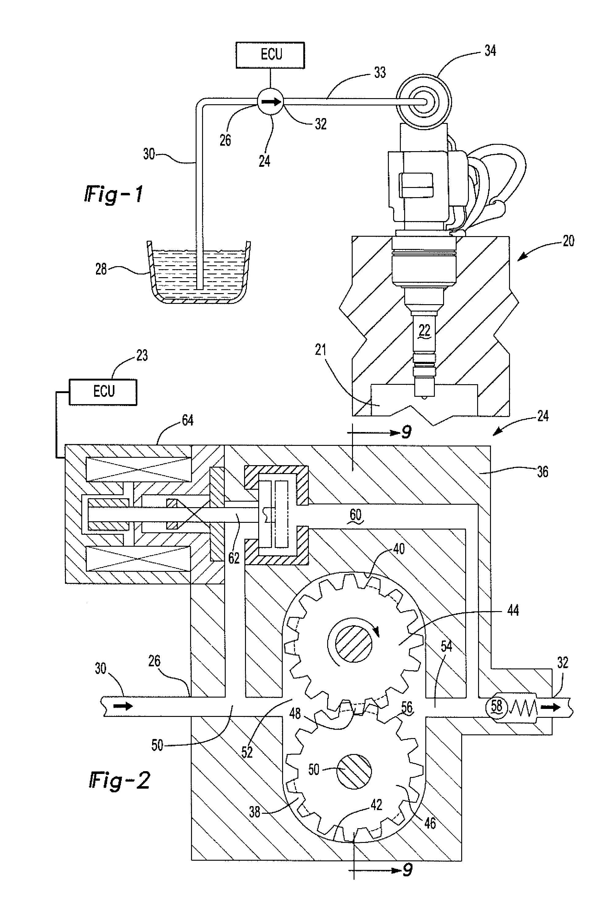
[0032]With reference first to FIG. 1, a block diagrammatic view is shown having an internal combustion four-cycle engine 20 which is preferably a direct injection engine. As such, the engine 20 includes a plurality of fuel injectors 22 (only one shown), each of which is open directly to a combustion chamber or cylinder 21 in the engine 20.

[0033]In order to supply fuel to the fuel injectors 22, a fuel pump 24 has an inlet 26 fluidly connected to a fuel tank 28 by a fuel supply line 30. An outlet 32 from the fuel pump 24 is fluidly connected by a fuel line 33 to a fuel rail 34 which, in turn, is fluidly connected to the fuel injectors 22. An engine control unit (ECU) 23 controls both the timing and duration of activation of the fuel injectors 22 during the operation of the engine 20.

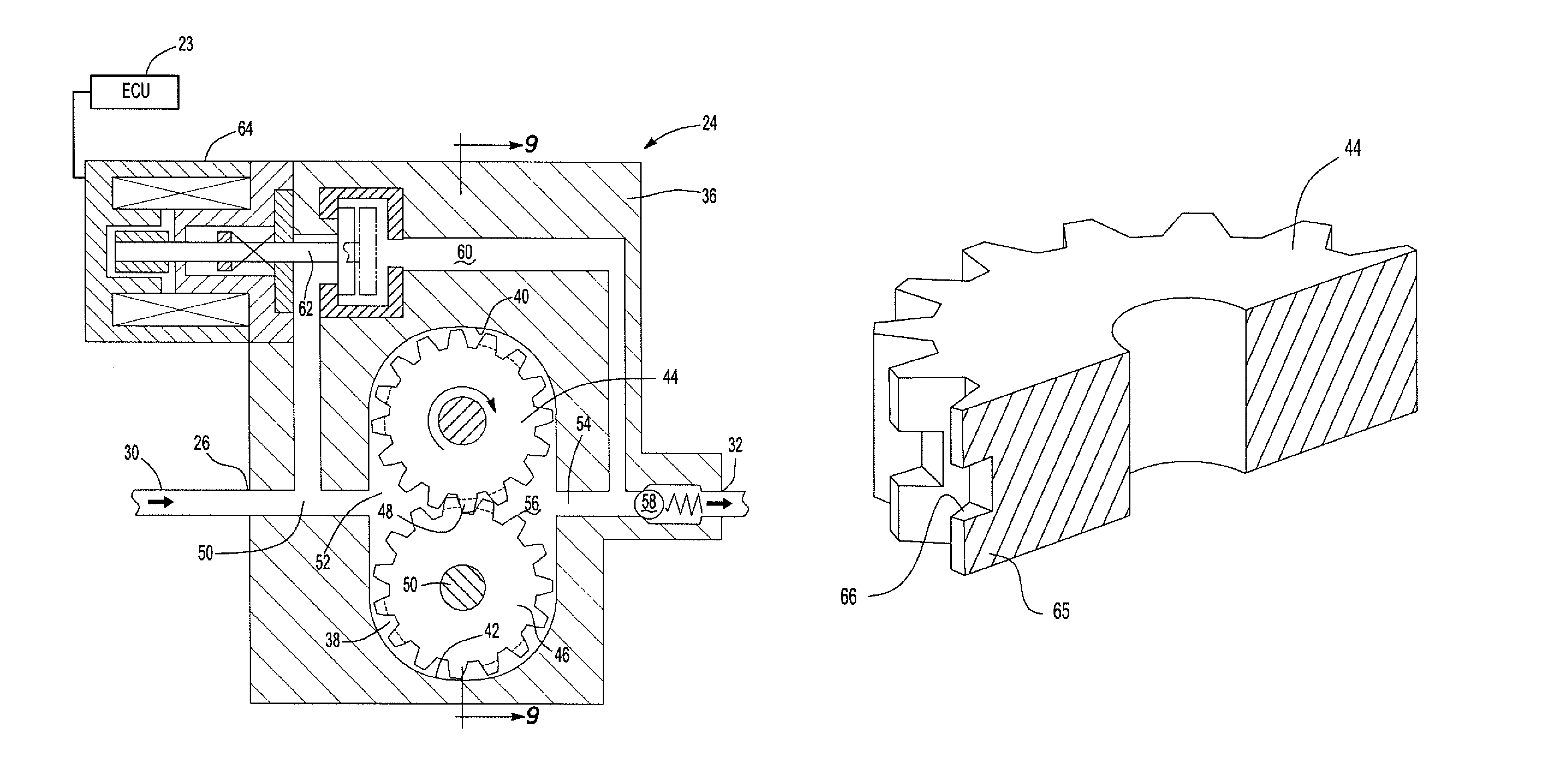
[0034]With reference now to FIG. 2, a cross-sectional view of the fuel pump 24 is shown. The fuel pump includes a housing 36 which defines a pump chamber 38. The pump chamber 38 is elongated in shape and i...


PUM


Abstract

A fuel pump for a direct injection internal combustion engine having a housing defining a pump chamber. Driven and idler toothed gears are rotatably mounted within the pump chamber so that the driven and idler gears are in mesh with each other at a predetermined location in the pump chamber. A fluid inlet is formed through the housing and open to an inlet subchamber in the pump chamber. A fluid outlet is also formed through the housing and open to an outlet subchamber in the pump chamber. A pressure relief passageway fluidly connects the inlet subchamber to the outlet subchamber and a valve is disposed in series with the pressure relief passageway. A control circuit controls the actuation of the valve to control the pump pressure at the pump outlet.

Description

BACKGROUND OF THE INVENTION[0001]I. Field of the Invention[0002]The present invention relates generally to pumps and, more particularly, to a fuel pump for an internal combustion engine and, particularly, a direct injection internal combustion engine.[0003]II. Description of Related Art[0004]There are different types of internal combustion engines used to propel automotive vehicles. However, direct injection internal combustion engines are becoming increasingly more common due to their fuel efficiency.[0005]In a direct injection internal combustion engine, the fuel injector is open directly to the combustion chamber rather than upstream from the intake valves as in the previously known multipoint fuel injectors. Since the fuel injectors are open directly to the cylinders or combustion chambers of the engine, the fuel injectors are subjected to high pressure. As such, it is necessary to supply fuel to the fuel injector at a pressure which is not only sufficient to overcome the pressu...

Claims


Application Information

Patent Timeline
Patent Type & Authority Patents(United States)
IPC IPC(8): F04C2/08F02M63/02F02M59/12F04C14/26F04C2/18F02M59/36
CPCF04C2/088F04C2/18F04C14/26F02M63/0245F02M59/12F02M59/366F02M63/0265F04C2210/1044
Inventor TANABE, YOSUKEABBAS, JASONSAIKALIS, GEORGE
Owner HITACHI LTD
Why Eureka
Try Eureka